TIDT385 May 2024
3.6 Smooth Transition
The smooth transition (no output voltage interruption) is shown in Figure 3-11 through Figure 3-28. For all waveforms:
- Channel 1 is output voltage, 1V / div
- Channel 2 is PoE Port 1 input current, 500mA / div
- Channel 4 is PoE Port2 input current, 500mA / div
- The time base is 100ms / div
- For all Expected Results, the output voltage remains within transient limits
- Standby indicates that the PoE PD MPS (maintain power signature) is active
Table 3-2 Transitions Between Two PoE
Inputs
| Case | Initial State | Transition | Expected Result |
|---|---|---|---|
| 1 | PoE Port 1 connected | Add PoE Port 2 | PoE Port 1 continues to power converter. PoE Port 2 connects in standby |
| 2 | PoE Port 2 connected | Add PoE Port 1 | Power transitions to PoE Port 1. PoE Port 2 stays connected in standby. |
| 3 | PoE Port 1 and Port 2 connected. PoE Port 1 powers converter. PoE Port 2 connected in standby. | Remove PoE Port 1 | Power transitions to PoE Port 2 |
| 4 | PoE Port 1 and Port 2 connected. PoE Port 1 powers converter, PoE Port 2 connected in standby. | Remove PoE Port 2 | PoE Port 1 continues to power converter |
 Figure 3-11 Case 1
 Figure 3-12 Case 2
 Figure 3-13 Case 3
 Figure 3-14 Case 4
Table 3-3 Transitions Between Single PoE
Input and Auxiliary
| Case | Initial State | Transition | Expected Result |
|---|---|---|---|
| 5 | PoE Port 1 connected | Add auxiliary | Auxiliary provides power. PoE Port 1 stays connected in standby. |
| 6 | PoE Port 2 connected | Add auxiliary | Auxiliary provides power. PoE Port 2 stays connected in standby. |
| 7 | Auxiliary connected | Add PoE Port 1 | Auxiliary continues to provide power. PoE Port 1 connects in standby. |
| 8 | Auxiliary connected | Add PoE Port 2 | Auxiliary continues to provide power. PoE Port 2 connects in standby. |
| 9 | PoE Port 1 and auxiliary connected | Remove auxiliary | Power transitions to PoE Port 1 |
| 10 | PoE Port 1 and auxiliary connected | Remove PoE Port 1 | Auxiliary continues to provide power. |
| 11 | PoE Port 2and auxiliary connected | Remove auxiliary | Power transitions to PoE Port 2 |
| 12 | PoE Port 2and auxiliary connected | Remove PoE Port 2 | Auxiliary continues to provide power. |
 Figure 3-15 Case 5
 Figure 3-16 Case 6
 Figure 3-17 Case 7
 Figure 3-18 Case 8
 Figure 3-19 Case 9
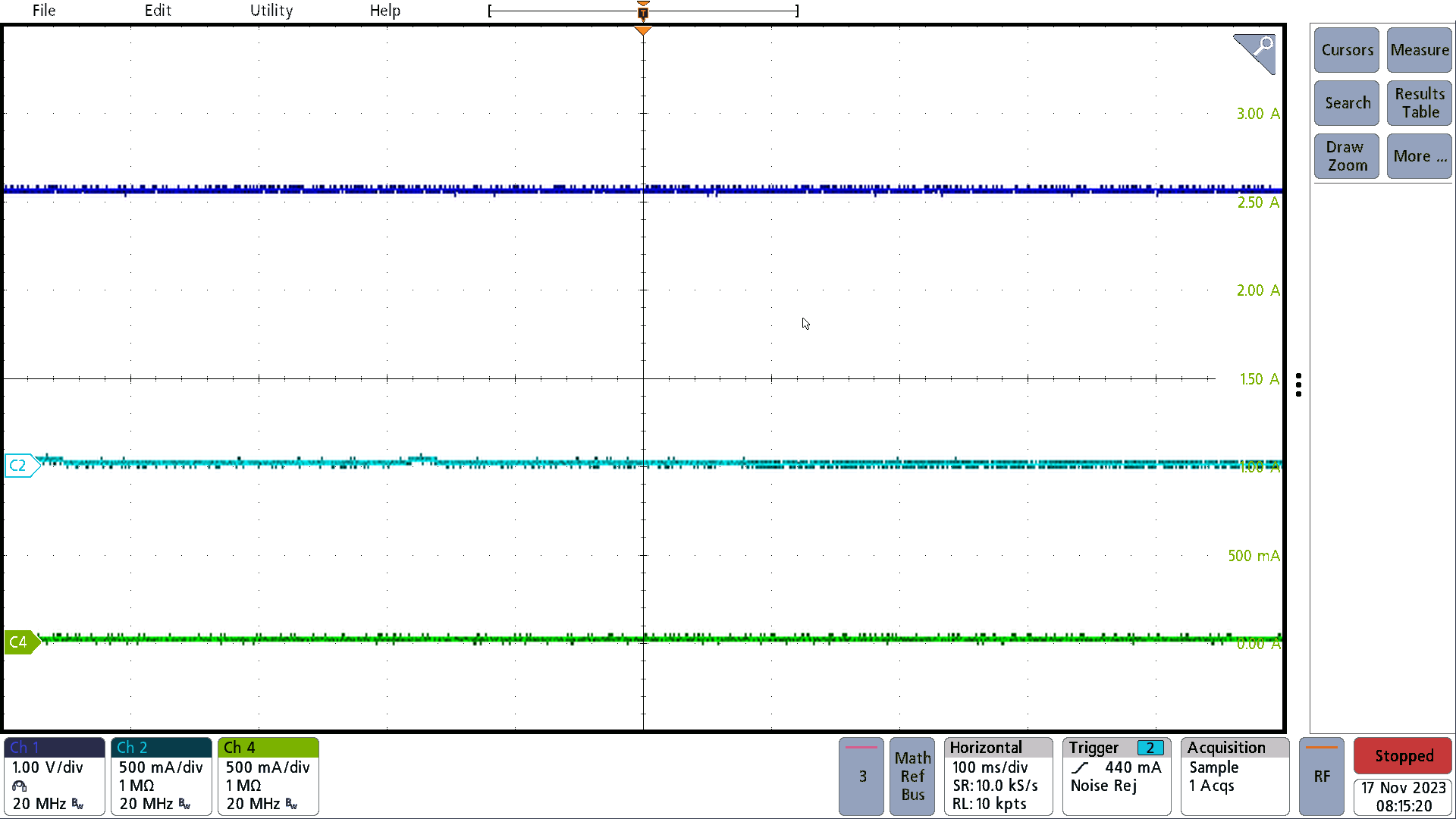 Figure 3-20 Case 10
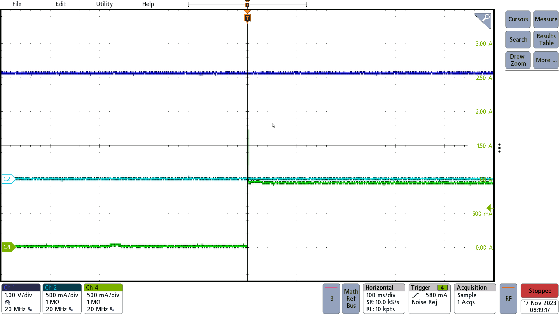 Figure 3-21 Case 11
 Figure 3-22 Case 12
Table 3-4 Transitions Between Dual PoE
Inputs and Auxiliary
| Case | Initial State | Transition | Expected Result |
|---|---|---|---|
| 13 | PoE Port 1, PoE Port 2 and Auxiliary connected | Remove Auxiliary | Power transitions to PoE Port 1. PoE Port 2 stays connected in standby. |
| 14 | PoE Port 1, PoE Port 2 and Auxiliary connected | Remove PoE Port 1 | Auxiliary continues to provide power. PoE Port 2 stays connected in standby. |
| 15 | PoE Port 1, PoE Port 2 and Auxiliary connected | Remove PoE Port 2 | Auxiliary continues to provide power. PoE Port 1 stays connected in standby. |
| 16 | PoE Port 1 and PoE Port 2 connected | Add Auxiliary | Power transitions to auxiliary. PoE Port 1 and Port 2 stay connected in standby. |
| 17 | PoE Port 1 and Auxiliary connected | Add PoE Port 2 | Auxiliary continues to provide power. PoE Port 1 stays connected in standby. PoE Port 2 connects in standby. |
| 18 | PoE Port 2 and Auxiliary connected | Add PoE Port 1 | Auxiliary continues to provide power. PoE Port 2 stays connected in standby. PoE Port 1 connects in standby. |
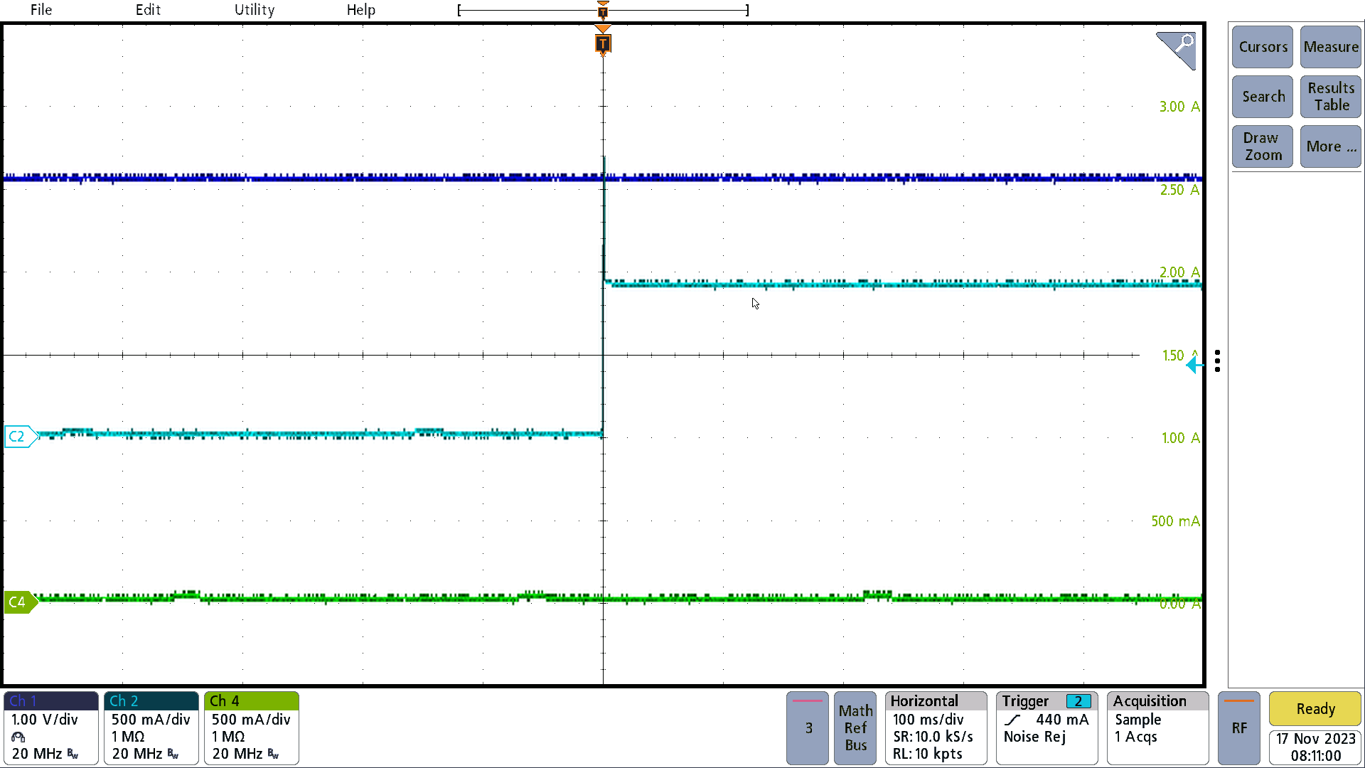 Figure 3-23 Case 13
 Figure 3-24 Case 14
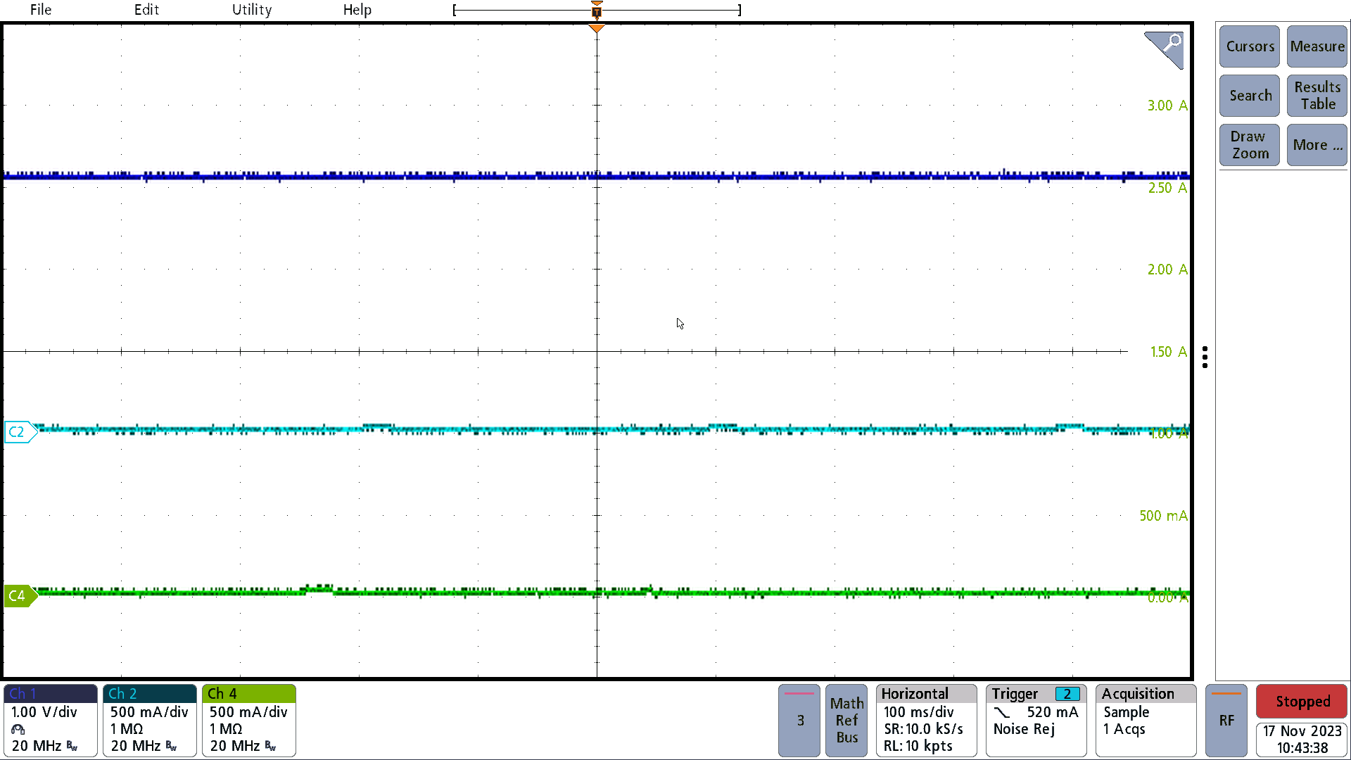 Figure 3-25 Case 15
 Figure 3-26 Case 16
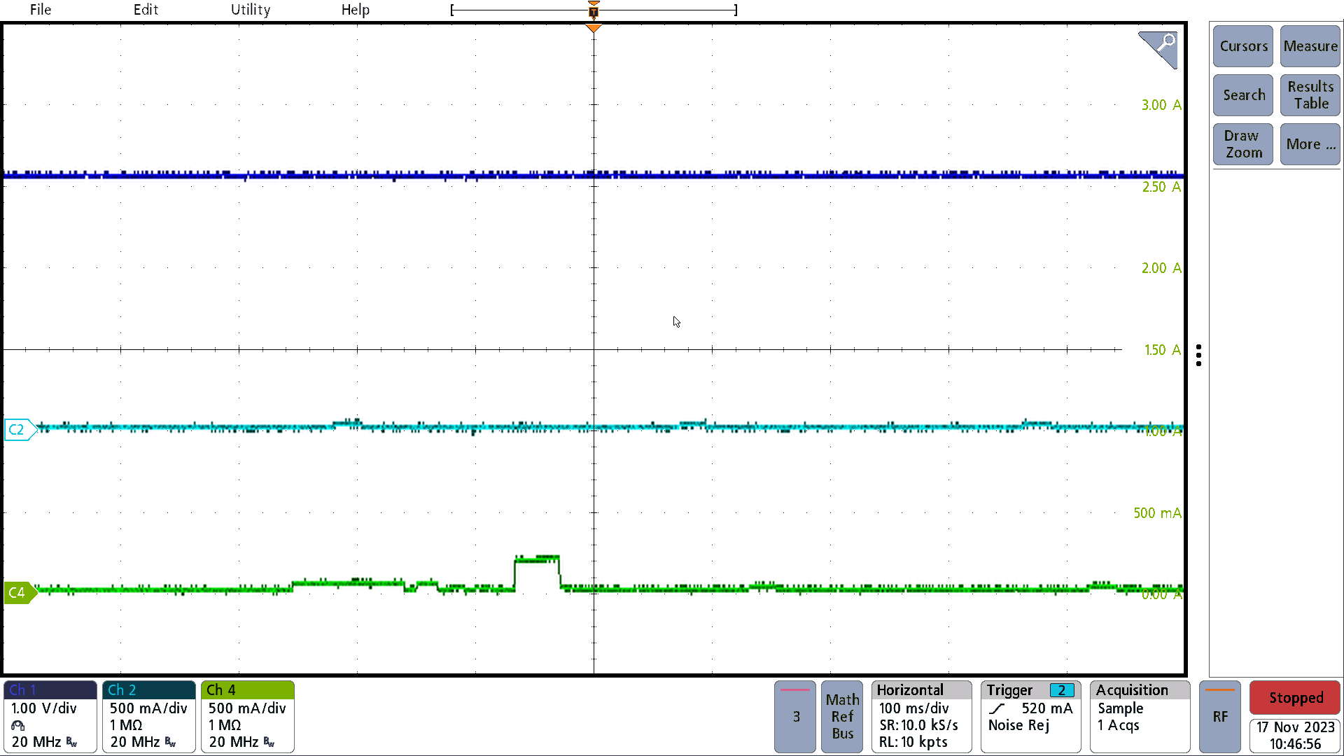 Figure 3-27 Case 17
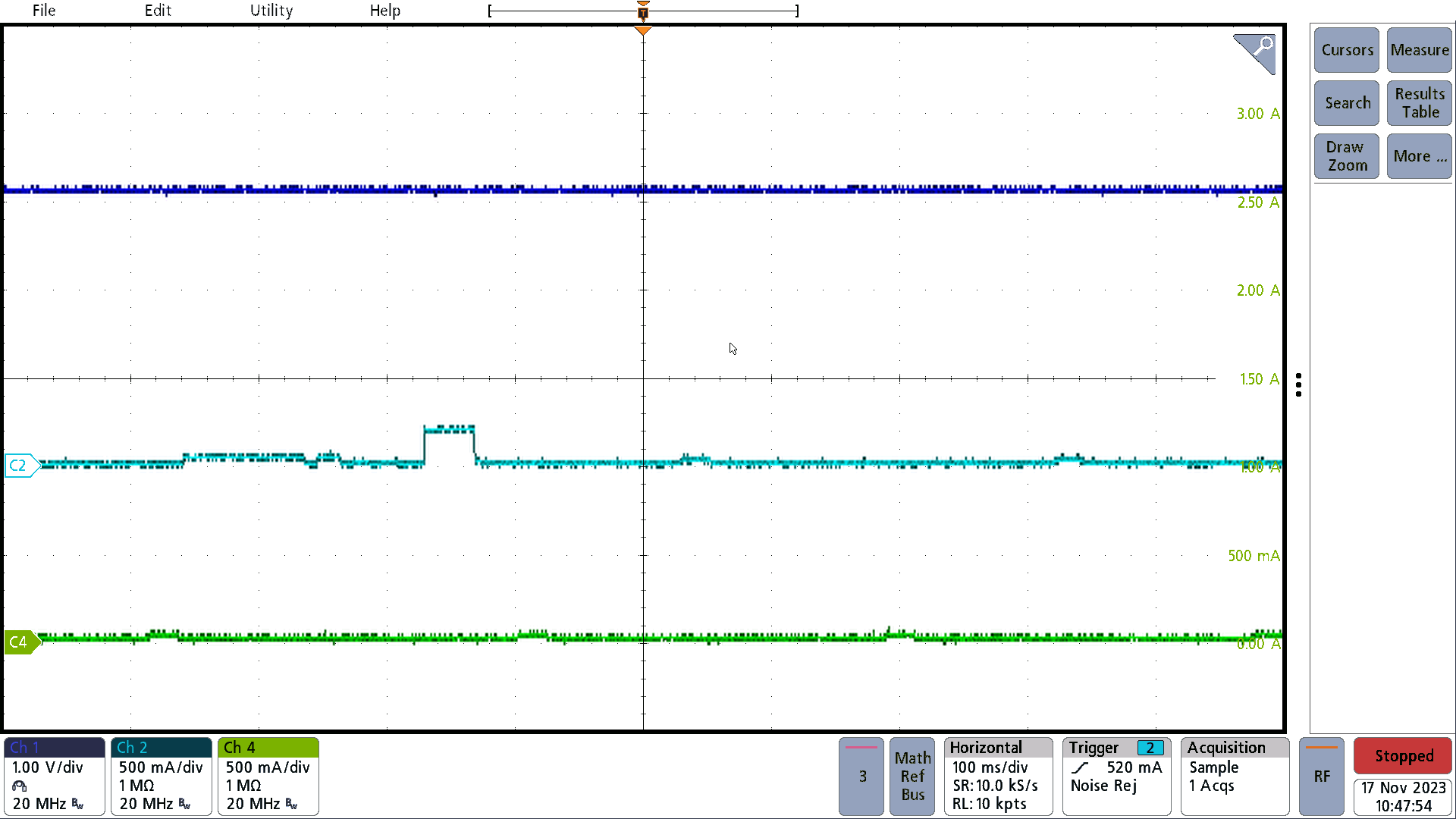 Figure 3-28 Case 18