TIDT391 April 2024
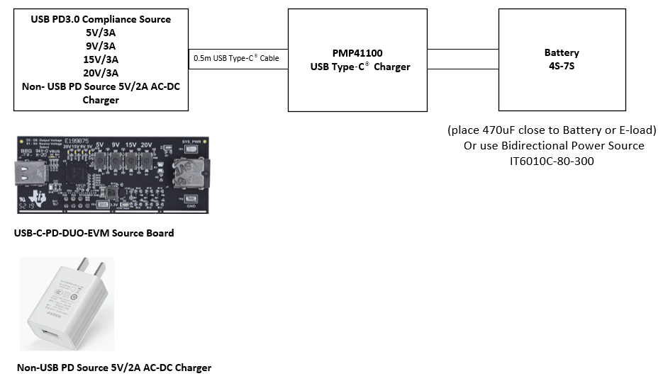
1.4 Test Setup
Place a 470μF, 100V bus capacitor physically close to the output terminal to avoid long cable connection to the battery side when performing the test.
 Figure 1-1 Test Setup
TIDT391 April 2024
Place a 470μF, 100V bus capacitor physically close to the output terminal to avoid long cable connection to the battery side when performing the test.
 Figure 1-1 Test Setup