TIDT394A May 2024 – January 2025
3.3 Short-Circuit Protection
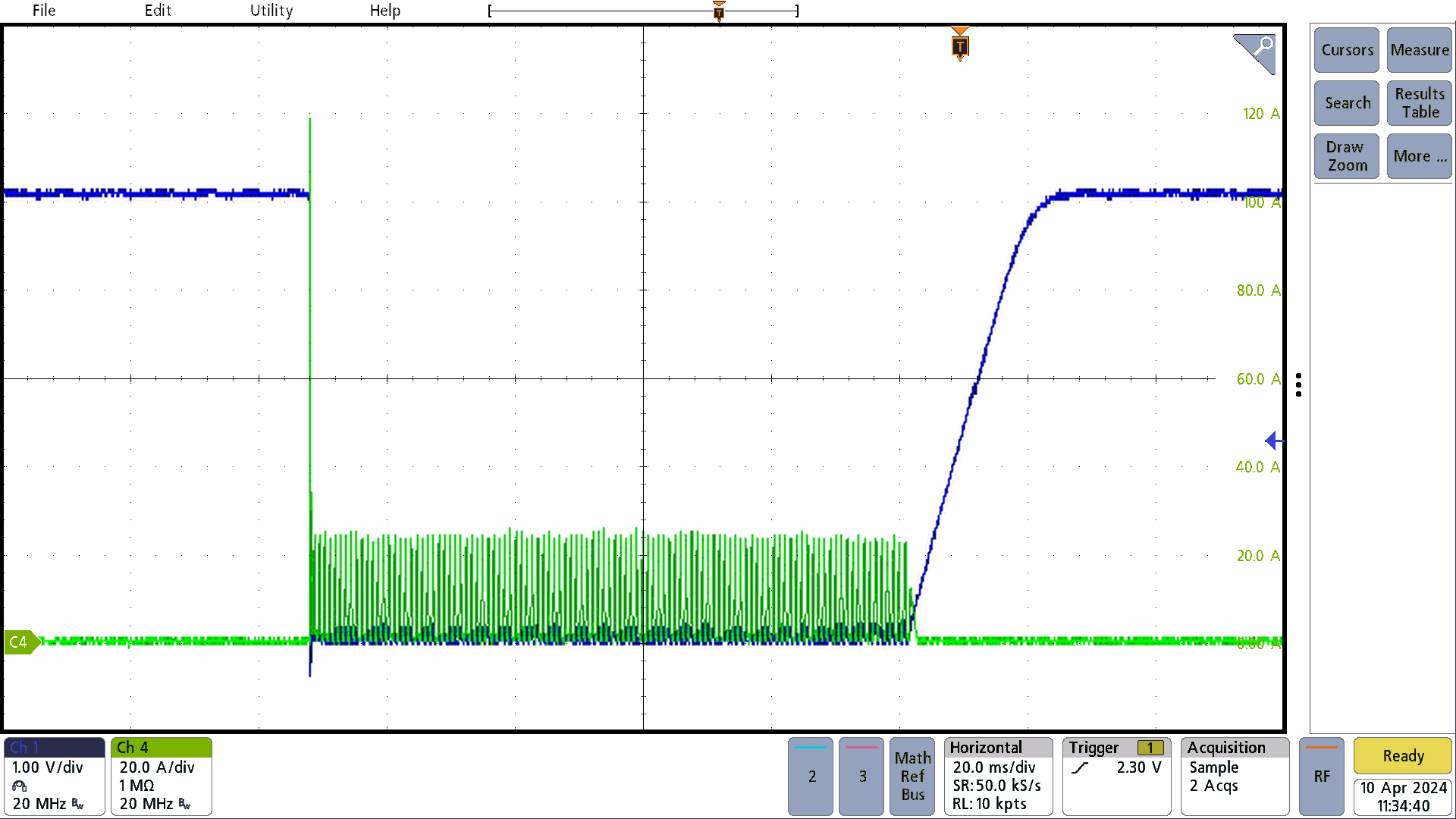
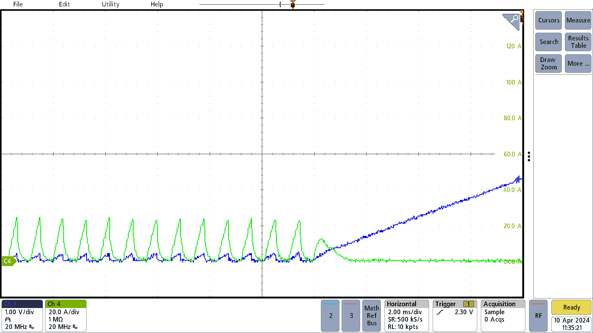
Output across J4 was shorted momentarily to illustrate that short-circuit protection functions effectively and the output voltage returns to the steady state value. The short-circuit protection is provided by the FAULT pin of the TPS7H5002-SP, which is optional. Ch 1: Output voltage, 1V/div Ch 4: Output current, 20A/div
 Figure 3-4 Short-Circuit Protection, 20ms/div
 Figure 3-5 Short-Circuit Protection, Zoomed in Window, 2ms/div