TIDT396 June   2024


  1.   1
  2.   Description
  3.   Features
  4.   Applications
  5. 1Test Prerequisites
    1. 1.1 Voltage and Current Requirements
    2. 1.2 Required Equipment
    3. 1.3 Considerations
    4. 1.4 Dimensions
  6. 2Testing and Results
    1. 2.1 Efficiency Graph
    2. 2.2 Efficiency Data
    3. 2.3 Thermal Image
    4. 2.4 Bode Plots
  7. 3Waveforms
    1. 3.1 Switching
    2. 3.2 Voltage Ripple
    3. 3.3 Load Transients
    4. 3.4 Turn-on Response

Bode Plots

Bode plots of control loop for ISOM8110 versus optocoupler. ISOM8110 shows significantly wider bandwidth than optocoupler.
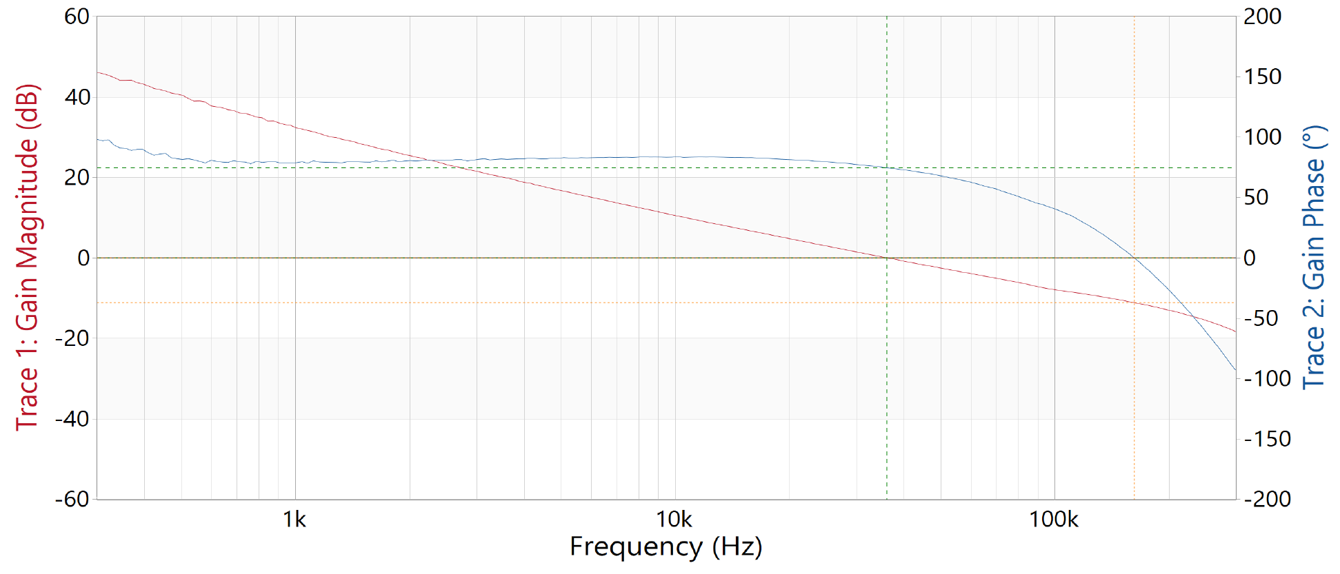
PMP23470 Bode Plot of Control Loop With
                        ISOM8110Figure 2-3 Bode Plot of Control Loop With ISOM8110

Bandwidth = 36.0kHz; Phase margin = 74.7 degrees; Gain margin = 11.1dB
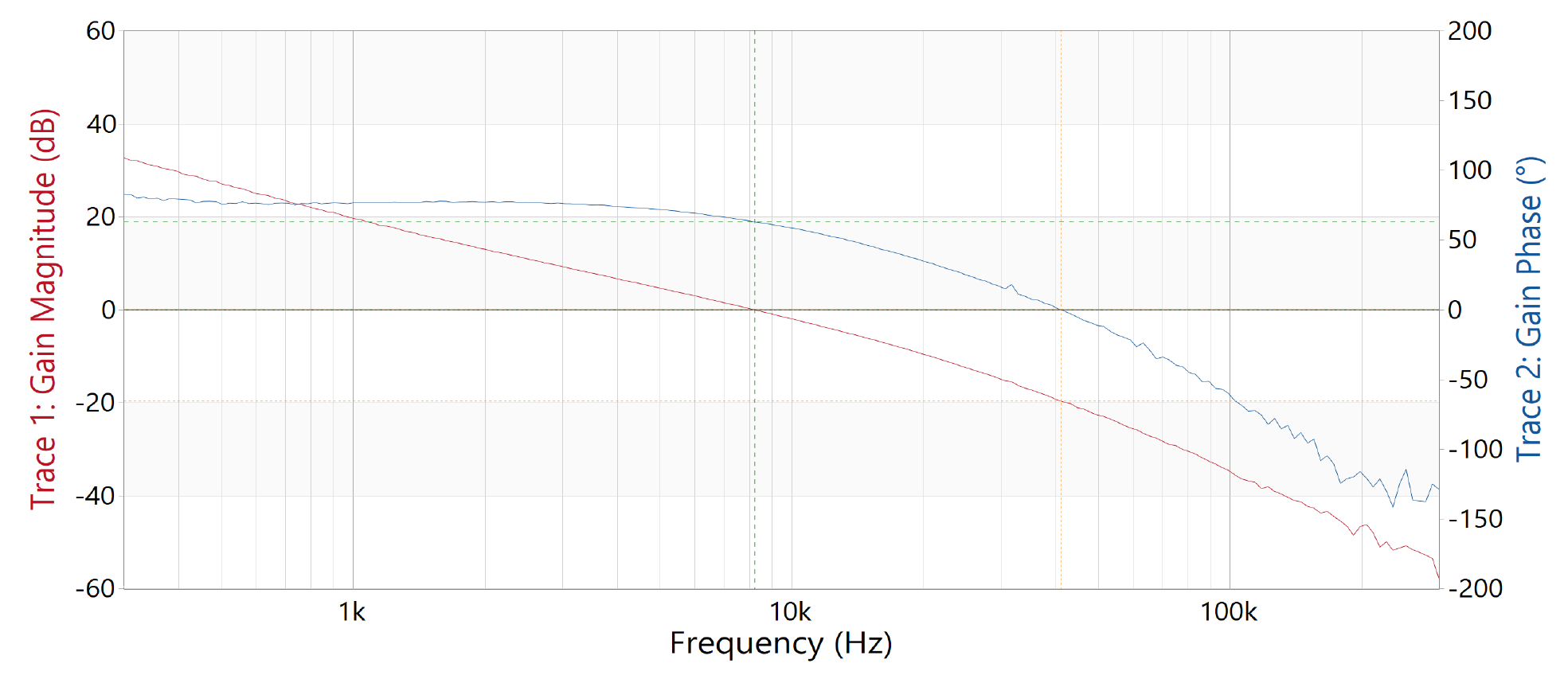
PMP23470 Bode Plot of Control Loop With
                        OptocouplerFigure 2-4 Bode Plot of Control Loop With Optocoupler

Bandwidth = 8.2kHz; Phase margin = 63.0 degrees; Gain margin = 19.6dB