TIDT400 July   2024


  1.   1
  2.   Description
  3.   Features
  4.   Applications
  5. 1Test Prerequisites
    1. 1.1 Voltage and Current Requirements
    2. 1.2 Suggested Equipment
    3. 1.3 General Texas Instruments High Voltage Evaluation (TI HV EMV) User Safety Guidelines
  6. 2Testing and Results
    1. 2.1 Load Regulation
    2. 2.2 Efficiency Graphs
    3. 2.3 Power Factor (PF) and Input Current Total Harmonic Distortion (iTHD)
    4. 2.4 Efficiency, PF, and THD Data
    5. 2.5 Thermal Images
    6. 2.6 Bode Plots
  7. 3Waveforms
    1. 3.1 Switching
    2. 3.2 Output Voltage Ripple
    3. 3.3 Output Current Ripple
    4. 3.4 Load Transients
    5. 3.5 Start-Up Sequence

Bode Plots

Figure 2-8 shows the Bode plot of the current loop.

Note: Test conditions: E-load constant voltage mode, 60V, 7A load
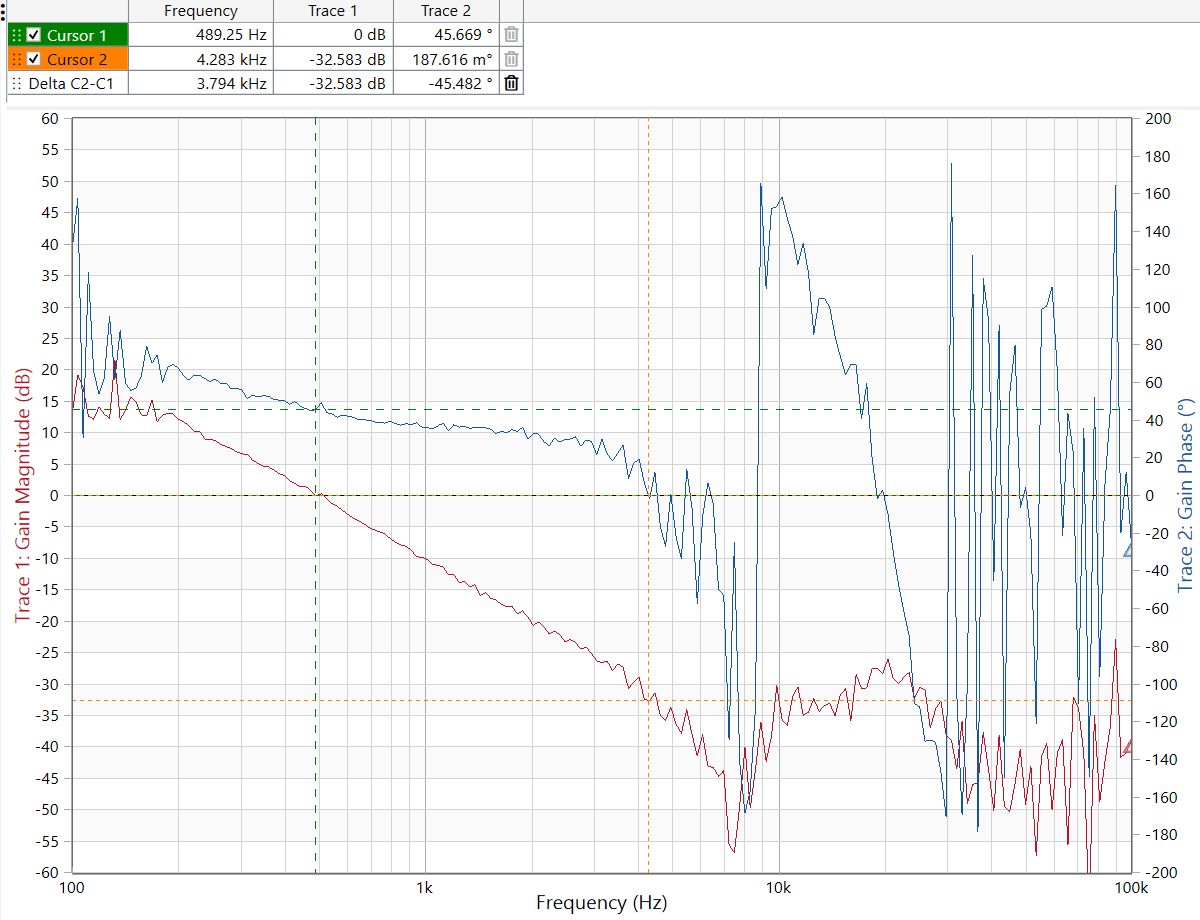
PMP23464 Bode Plot of CC Mode Figure 2-8 Bode Plot of CC Mode

Figure 2-9 shows the Bode plot of the voltage loop.

Note: Test conditions: E-load constant current mode, 71.4V, 6.5A load
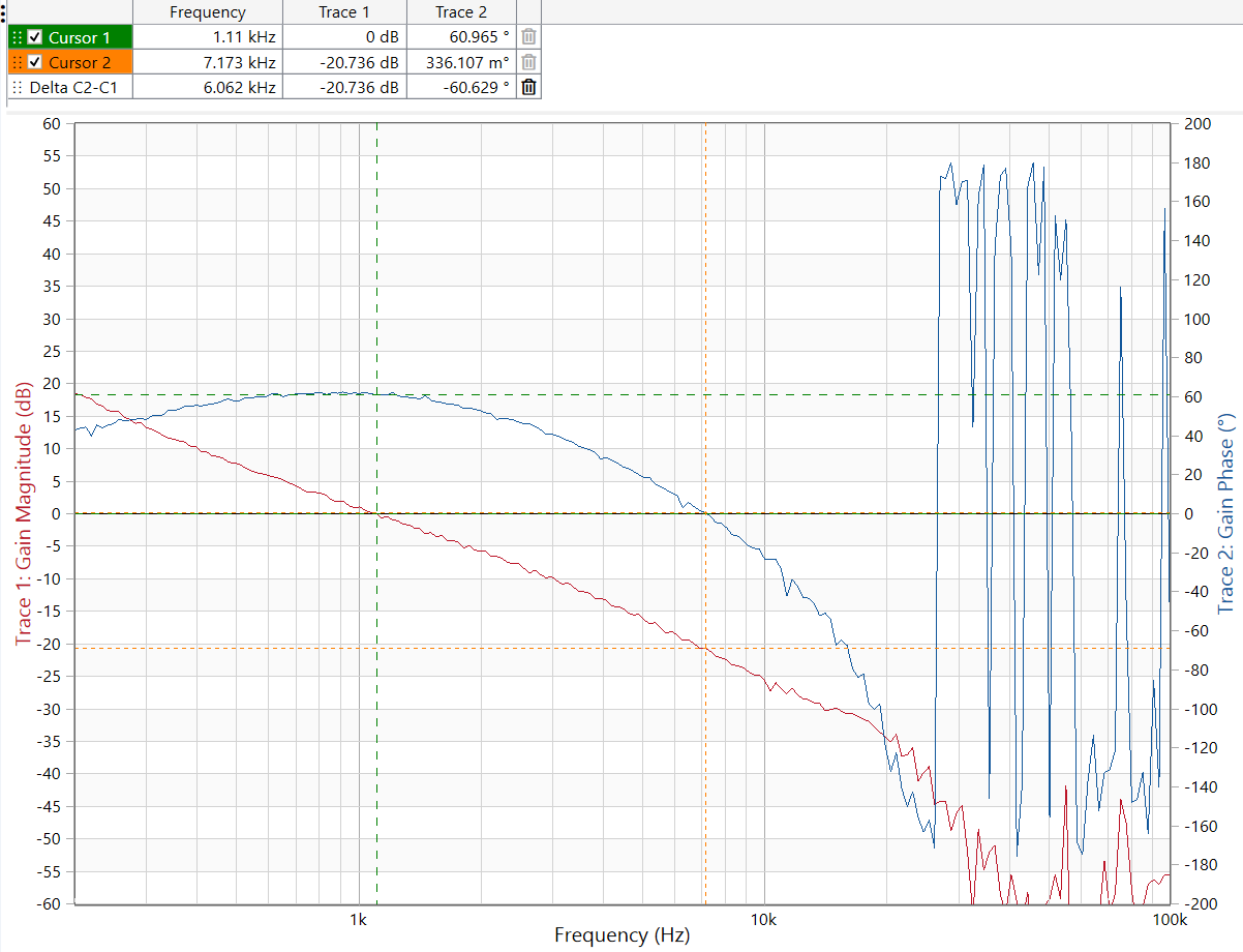
PMP23464 Bode Plot of CV ModeFigure 2-9 Bode Plot of CV Mode