TIDT400 July 2024
2.5 Thermal Images
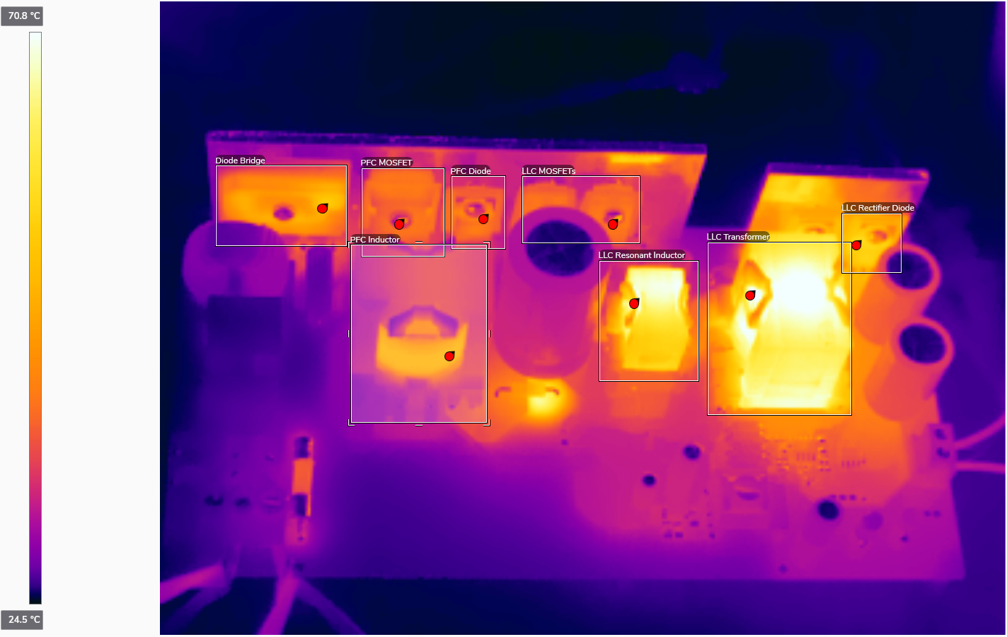
Thermal images are shown in Figure 2-6.
 Figure 2-6 TA = 25.0°C, 115V,
60Hz Input, Full Load
Figure 2-6 TA = 25.0°C, 115V,
60Hz Input, Full LoadNote: Tested after 20 minutes
operation, with 12V, 0.25A fan cooling.
Table 2-2 Component Temperature, 115V,
60Hz Input, Full Load
| COMPONENT | TEMPERATURE (°C) |
|---|---|
| D1 Rectifier Bridge | 56.2 |
| Q1 PFC MOSFET | 45.7 |
| D5 PFC Diode | 45.3 |
| L4 PFC Choke | 52.0 |
| Q7, Q8 LLC MOSFETs | 56.7 |
| L5 LLC Resonant Inductor | 71.5 |
| T1 LLC Transformer | 75.2 |
| D11, D12 LLC Rectifier Diodes | 59.1 |
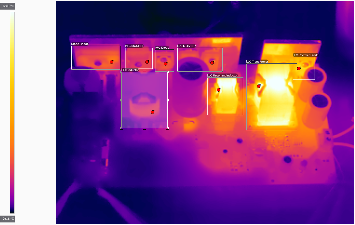
 Figure 2-7 TA = 25.0°C, 230V,
50Hz Input, Full Load
Figure 2-7 TA = 25.0°C, 230V,
50Hz Input, Full LoadTable 2-3 Component Temperature, 230V,
50Hz Input, Full Load
| COMPONENT | TEMPERATURE (°C) |
|---|---|
| D1 Rectifier Bridge | 41.4 |
| Q1 PFC MOSFET | 37.3 |
| D5 PFC Diode | 39.0 |
| L4 PFC Choke | 34.9 |
| Q7, Q8 LLC MOSFETs | 56.7 |
| L5 LLC Inductor | 70.4 |
| T1 LLC Transformer | 72.0 |
| D11, D12 LLC Rectifier Diodes | 58.4 |