TIDT403A August 2024 – December 2024
2.3 Thermal Performance
A thermal image is shown in Figure 2-7. Not too much thermal data can be gained from the top view due to SR card and GaN cards being vertical to main board and screwed to water-cooling heat sink.
Test condition: 400Vin, 16Vout, room temperature, 20°C degree liquid coolant.
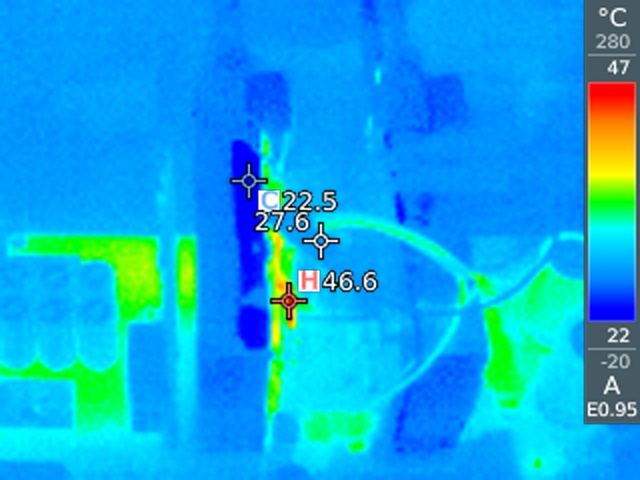 Figure 2-7 Thermal Image at 180Aout, Top View
The magnetics of HV to LV DC/DC converter contain a transformer and a choke. The leakage of Transformer is used as resonant inductor in PSFB topology. Figure 2-8 is the mechanical drawing and dimensions of magnetics. Figure 2-9 shows the position of thermocouple. Figure 2-10 shows the test result when 400Vin, 16Vout, 100Aout with 20°C degree liquid coolant. Figure 2-11 shows the test result when 400Vin, 16Vout, 180Aout with 20 C degree liquid coolant.
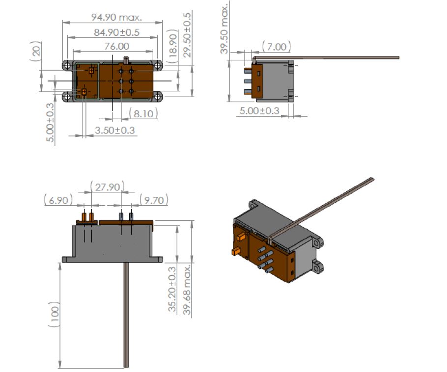 Figure 2-8 Mechanical Drawing and Dimensions
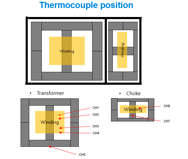 Figure 2-9 Position of Thermocouple
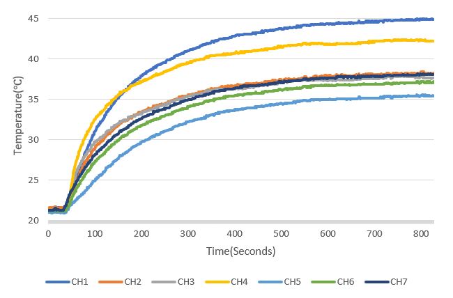 Figure 2-10 Magnetic Thermal Performance at 100Aout
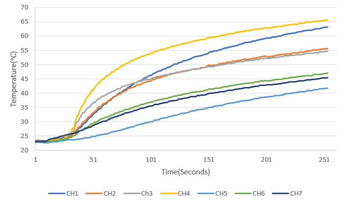 Figure 2-11 Magnetic Thermal Performance at 180Aout