TIDT403A August 2024 – December 2024
1.3 Considerations
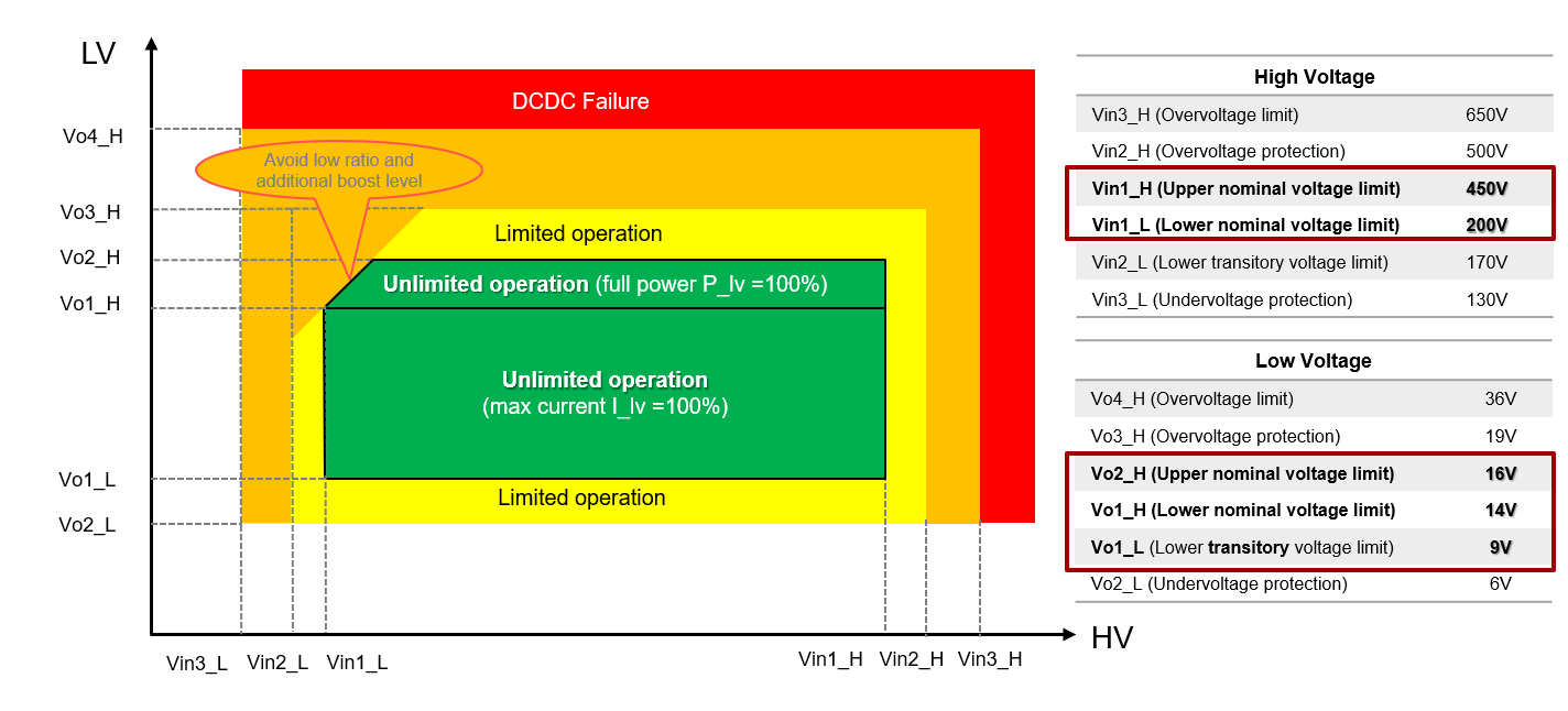
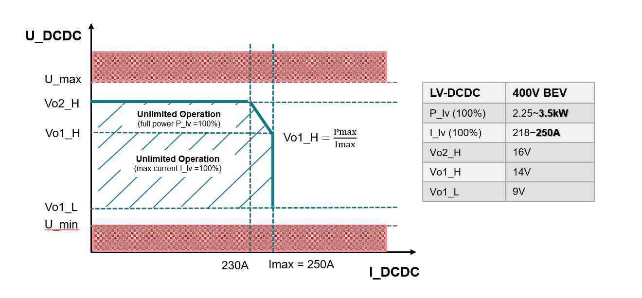
Commonly, for high-voltage to low-voltage DC/DC applications, the input and output voltage both are in a wide range. Figure 1-1 shows the relationship with input voltage and output voltage. The maximum output voltage is 14V while input voltage drops to 200V. When the output voltage is between 14V and 16V, the converter can output full power with the current derated. When the output voltage is between 9V and 14V, the converter can output maximum current with power derated. The details are shown in Figure 1-2.
 Figure 1-1 Input Voltage and Output Voltage
 Figure 1-2 Maximum Output Power and Maximum Output Current