TIDT407 October 2024
2.3 Thermal Images
Figure 2-7 through Figure 2-16 show the thermal images at full power charge mode and OTG mode. All images were captured at 25ºC ambient temperature, after a 30-minute warm up.
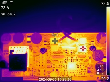 Figure 2-7 Charge Mode From 28Vin to 50V 12S
Battery
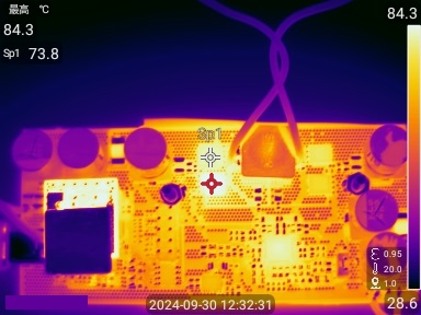 Figure 2-9 OTG mode, 42V Battery 10S to 48V 5A
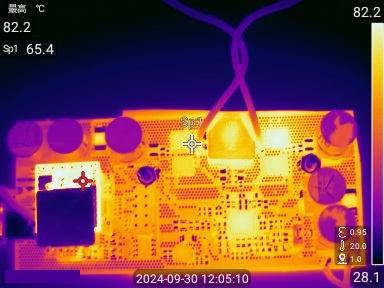 Figure 2-11 OTG Mode, 50V Battery 12S to 36V 5A
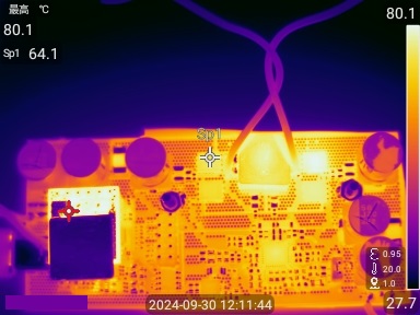 Figure 2-13 OTG Mode, 50V Battery 12S to 20V 5A
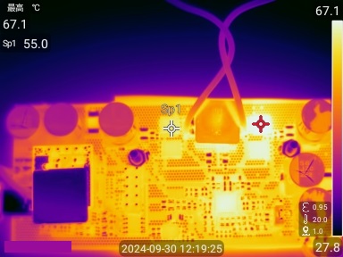 Figure 2-15 OTG Mode, 50V Battery 12S to 9V 3A
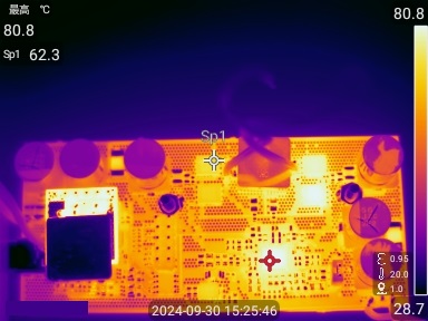 Figure 2-8 Charge Mode From 48Vin to 50V 12S
Battery
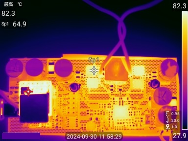 Figure 2-10 OTG Mode, 50V Battery 12S to 48V 5A
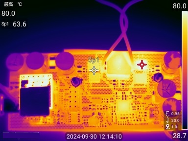 Figure 2-12 OTG Mode, 50V Battery 12S to 28V 5A
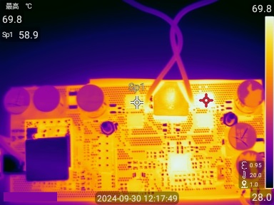 Figure 2-14 OTG Mode, 50V Battery 12S to 15V 3A
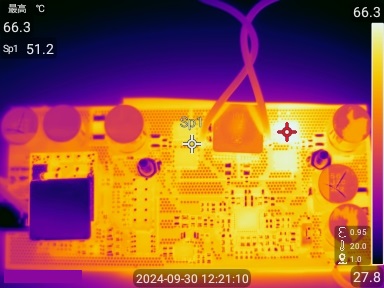 Figure 2-16 OTG Mode, 50V Battery 12S
to 5V 3A