TIDT426 December 2024
3.1 Switching
The waveforms of switching nodes at different output voltages with full load conditions are shown in Figure 3-1 through Figure 3-8.
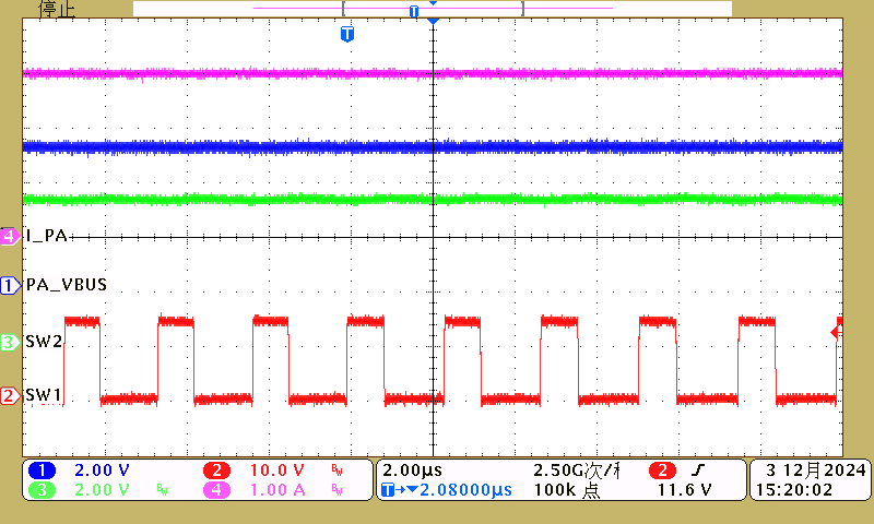 Figure 3-1 PORTA, 14V Input, 5V, 3A Load
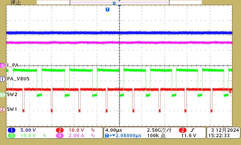 Figure 3-3 PORTA, 14V Input, 15V, 3A Load
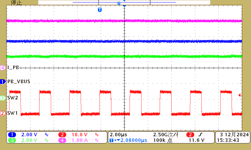 Figure 3-5 PORTB, 14V Input, 5V, 3A Load
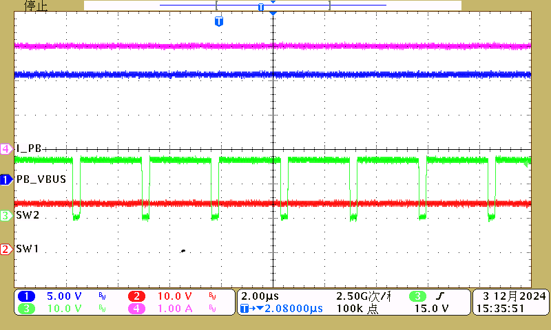 Figure 3-7 PORTB, 14V Input, 15V, 3A Load
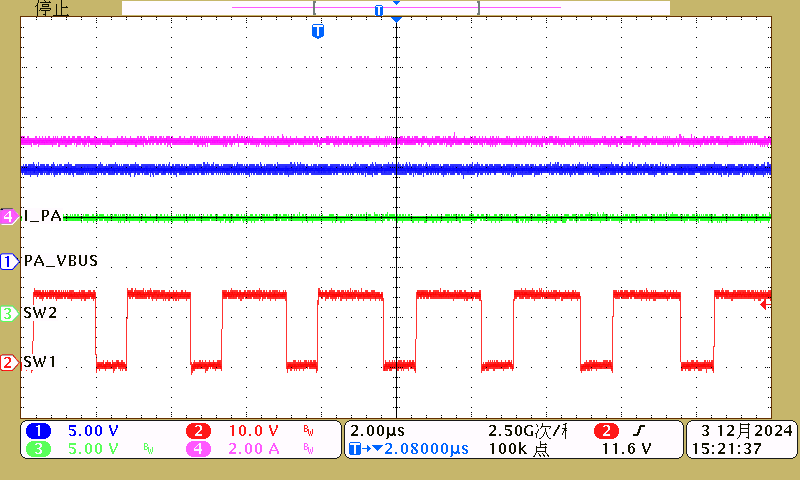 Figure 3-2 PORTA, 14V Input, 9V, 3A Load
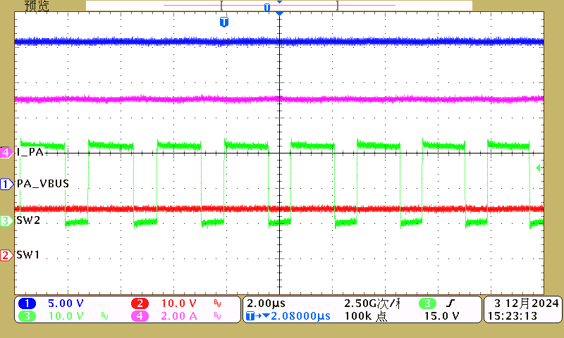 Figure 3-4 PORTA, 14V Input, 20V, 3A Load
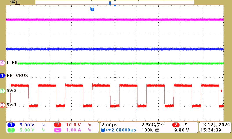 Figure 3-6 PORTB, 14V Input, 9V, 3A Load
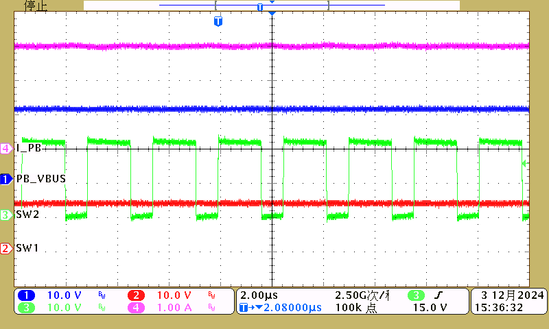 Figure 3-8 PORTB, 14V Input, 20V, 3A Load