TIDUAY6E November 2015 – March 2020
3.1 Block Diagram
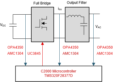
A typical inverter comprises of a full bridge that is constructed with four switches, which can be modulated using pulse width modulation (PWM), and a filter for the high-frequency switching of the bridge, as shown in Figure 1. An inductor capacitor (LC) output filter is used on this reference design.
