TIDUAY6E November 2015 – March 2020
4.1.2.3.1.5 Running the Code
- Run the project by clicking the green arrow button.
- In the watch view, check if the guiVbus, guili, guiIo, and guiVo variables are updating periodically.
- Set the value of rlyConnect to 1, which will connect the relay, and the user will hear a clicking sound.
- Set the clearlnvTrip variable to 1.
- EmPwm1Regs.TZFLG.all appears.
- Set EPwm1Regs to zero, and the boardStatus will update to boardStatus_NoFault.
- Set the invModIndex to 0.5.
- With a resistance of 100 Ω connected at the output, first raise the input DC bus up slowly to 50 V. Observe the current and voltage waveform on the scope. AC current and voltage waveform should appear albeit at a low voltage. Now, slowly increase the DC bus to 380 V.
- Observe the AC waveform on the oscilloscope for the voltage and current.
- Observe the clean AC waveform (owing to the low frequency switching, a sharp pulse around the zero crossing is expected).
- Check the frequency of the generated AC waveform.
- Confirm that the frequency matches the value entered on the powerSUITE page.
- Confirm the AC measurement is correct by viewing the gui_Vrms and gui_Irms values.
- For the DC bus of 380 V, and a 100-Ω output with a 0.5 inverter modulation index, the output voltage will be close to guiVrms = 133, and the current will be guiIrms = 1.35 A for SDFM sensing; for ADC sensing, the measured current is going to be higher because the inductor current is measured instead of the output current.
- The AC voltage may be modulated by changing the modulation index through the watch window.
- The check for this build is now completed.
- Verify the following items on successful completion of the build.
- Inverter modulation scheme and generation of correct AC waveform.
- Sensing of voltages, currents, and scalings are correct.
- Interrupt generation and execution of the build 1 code in the inverter ISR.
- To power down, set invModIndex to zero.
- Set rlyConnect to zero.
- Slowly decrease the DC bus voltage to 0 V.
- The controller can now be halted, and the debug connection is terminated.
NOTE
If there are inconsistencies in the measured valued and the actual values, confirm that the hardware and enter the correct values on the powerSUITE page for the scaling of voltages and currents.
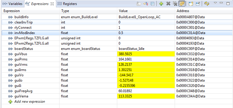
Figure 24 shows the build level 1 expressions view with power measurement.
 Figure 24. Build Level 1 Expressions View With Power Measurement
 Figure 25 shows the graph window inside CCS that was set up previously (see Figure 23). The measured voltage and current AC waveform can be observed on these graphs.
Figure 25 shows the graph imported in the build level 1 through the graph1.graphprop file, displaying the measured per-unit voltage and current values.
If nothing is observed in the graph, put dlog1.status in the Expression window, and if it is set to 0, set it to 1. Also, if multiple AC cycle need to be observed, enter dlog1.prescalar to be greater than 1; for example, it can be set to be 5.
 Figure 25. Build Level 1 Graph.1.GraphProp File Showing Measured Per-Unit Voltage and Current Values
 NOTE
In case CCS loses connection at any point, bring the system to a safe stop by bringing the input voltage to zero and then disconnecting the JTAG cable and reconnecting.