TIDUC07 March 2022
3.3.6 DRV5055 Off Axis Result
For this device, the sensitivity matching of the sensors requires some normalization by the controller before performing calculations on the captured analog data. This alignment requires sensors spread about the magnet by 90° and occupies more space than a single TMAG5170, and presents additional opportunity for mechanical misalignment. Despite these drawbacks, it is still possible to follow the same method of harmonic adjustment to eliminate angle error.
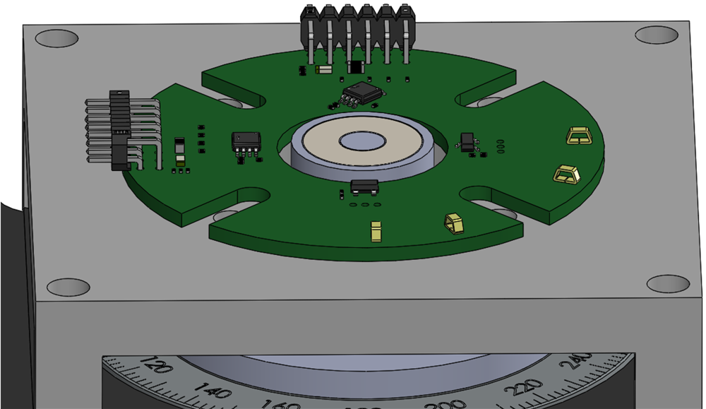
 Figure 3-21 DRV5055 Off-Axis
Configuration
Figure 3-21 DRV5055 Off-Axis
ConfigurationDRV5055 Off-Axis Mechanical Angle Error shows the resulting pre-calibrated error captured for this alignment. The challenge observed using this configuration is that the number of mechanical errors possible in the system are now doubled with a second sensor. This produces a more complex error profile. Despite this, the same procedure for calibration applies and yields excellent results.
| HARMONIC | αi | βi |
|---|---|---|
| 1 | –7.3 | 0.35 |
| 2 | 1.17 | 0.22 |
| 3 | –2.23 | 0.28 |
| 4 | –0.81 | –0.14 |
| 5 | –0.075 | 0.01 |
| 6 | –0.035 | 0.02 |
| 7 | –0.03 | –0.005 |
| 8 | –0.01 | 0 |
DRV5055 Off-Axis Calibrated Angle Error shows the resulting error after applying the harmonic data.