TIDUC07 March   2022


  1.   Description
  2.   Resources
  3.   Features
  4.   Applications
  5.   5
  6. 1System Description
  7. 2System Overview
    1. 2.1 Block Diagram
    2. 2.2 Highlighted Products
      1. 2.2.1 TMAG5170
      2. 2.2.2 DRV5055A4
    3. 2.3 Design Considerations
      1. 2.3.1 Magnet Selection
      2. 2.3.2 Magnet Shape
      3. 2.3.3 Magnet Rotation Speed
      4. 2.3.4 Sensor Location
      5. 2.3.5 Expected Performance
      6. 2.3.6 Layout for Sensor Location
      7. 2.3.7 45° Alignment
  8. 3Hardware, Software, Testing Requirements, and Test Results
    1. 3.1 Hardware Requirements
    2. 3.2 Test Setup
      1. 3.2.1 Test Equipment
      2. 3.2.2 Test Hardware Configuration
      3. 3.2.3 Test Software Configuration and Initial Data Capture
    3. 3.3 Test Results
      1. 3.3.1 Calibration Methods
      2. 3.3.2 TMAG5170 On-Axis
      3. 3.3.3 TMAG5170 In-Plane
      4. 3.3.4 TMAG5170 Off-Axis
      5. 3.3.5 TMAG5170 45° Alignment
      6. 3.3.6 DRV5055 Off Axis Result
  9. 4Design and Documentation Support
    1. 4.1 Design Files
      1. 4.1.1 Schematics
      2. 4.1.2 BOM
    2. 4.2 Tools and Software
    3. 4.3 Documentation Support
    4. 4.4 Support Resources
    5. 4.5 Trademarks

Magnet Selection

The magnet selected for testing was R834DIA, an N42 Grade diametric ring magnet. The magnet is specified with an inner diameter of 4.75 mm (0.1875 in) and an outer diameter of 12.7 mm (0.5 in). The magnet thickness is 6.35 mm (0.25 in).
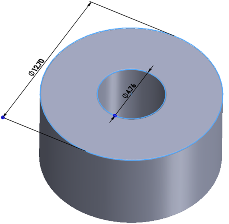
GUID-20220208-SS0I-BPWH-PK05-ZMMTMXJ3M5DS-low.png Figure 2-2 Diametric Ring Magnet