TIDUCL0 January 2017
- 1 Description
- 2 Resources
- 3 Features
- 4 Applications
- 5 Design Images
- 6 System Overview
-
7 System Design Theory
- 7.1 Power Stage Design—Battery Power Input to the Board
- 7.2 Power Stage Design—Three-Phase Inverter
- 7.3 Power Stage Design—DRV8323 Gate Driver
- 7.4 Power Stage Design—18-V to 3.3-V DC-DC Converter
- 7.5 Power Stage Design —Microcontroller MSP430
- 7.6 Power Stage Design—Hall Sensor Interface
- 7.7 Temperature Sensing
- 7.8 Power Stage Design—External Interface Options and Indications
- 8 Getting Started Hardware and Software
- 9 Testing and Results
- 10Design Files
- 11Software Files
- 12Related Documentation
- 13Terminology
- 14About the Author
8.1.1 Connector Configuration of TIDA-00774
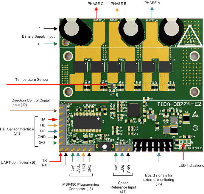
Figure 15 shows the TIDA-00774 connector configuration, which features the following:
- Two-terminal input for power supply: This pin is used to connect the input DC supply from the battery. The positive and negative terminals can be identified as shown in Figure 15.
- Three-terminal output for motor winding connection: The phase output connections for connecting to the three-phase BLDC motor winding, marked as PHASE A, PHASE B, and PHASE C as shown in Figure 15.
- 3-pin connector J1: This connector can be used to interface an external potentiometer for speed reference. The two fixed terminals of the potentiometer should be connected to 3V3 pin and GND pin. The mid-point of the potentiometer should be connected to the POT pin of the connector.
- 2-pin connector J2: This connector is used for the motor direction change. Externally shorting or opening this connector will change the direction of rotation of the motor.
- 4-pin connector J3: This is the programming connector for the MSP430F5132 MCU. The two-wire Spy-Bi-Wire protocol is used to program the MSP430F5132.
- 5-pin connector J4: This is the interface for connecting the Hall position sensors from the motor
- 14-pin connector J5: All the signals in the board are available at this pin. This connector can be used for external monitoring or control.
- 2-pin connector J6: This connector is used for external UART communication interface. The RX and TX pins are available enabling the communication with external BLE or Wi-IFi.
 Figure 15. TIDA-00774 PCB Connectors