TIDUCL0 January 2017
- 1 Description
- 2 Resources
- 3 Features
- 4 Applications
- 5 Design Images
- 6 System Overview
-
7 System Design Theory
- 7.1 Power Stage Design—Battery Power Input to the Board
- 7.2 Power Stage Design—Three-Phase Inverter
- 7.3 Power Stage Design—DRV8323 Gate Driver
- 7.4 Power Stage Design—18-V to 3.3-V DC-DC Converter
- 7.5 Power Stage Design —Microcontroller MSP430
- 7.6 Power Stage Design—Hall Sensor Interface
- 7.7 Temperature Sensing
- 7.8 Power Stage Design—External Interface Options and Indications
- 8 Getting Started Hardware and Software
- 9 Testing and Results
- 10Design Files
- 11Software Files
- 12Related Documentation
- 13Terminology
- 14About the Author
9.2.1.5 VGS Skew of Parallel FETs During Switching
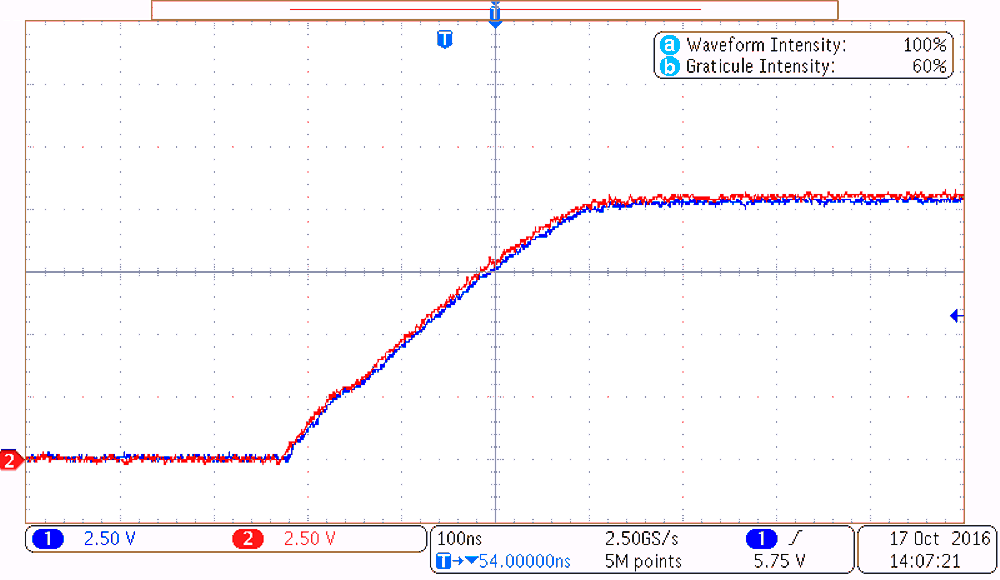
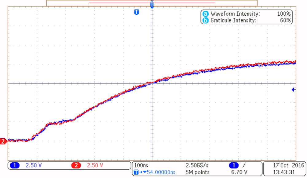
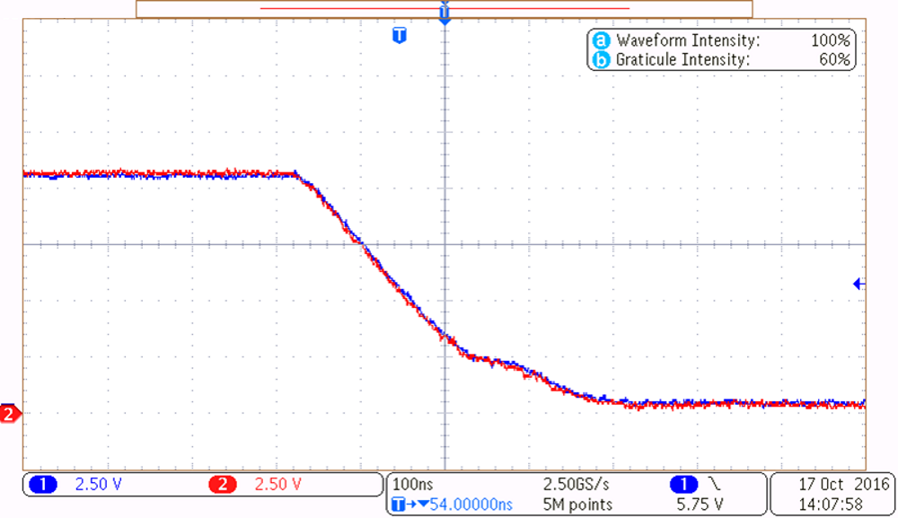
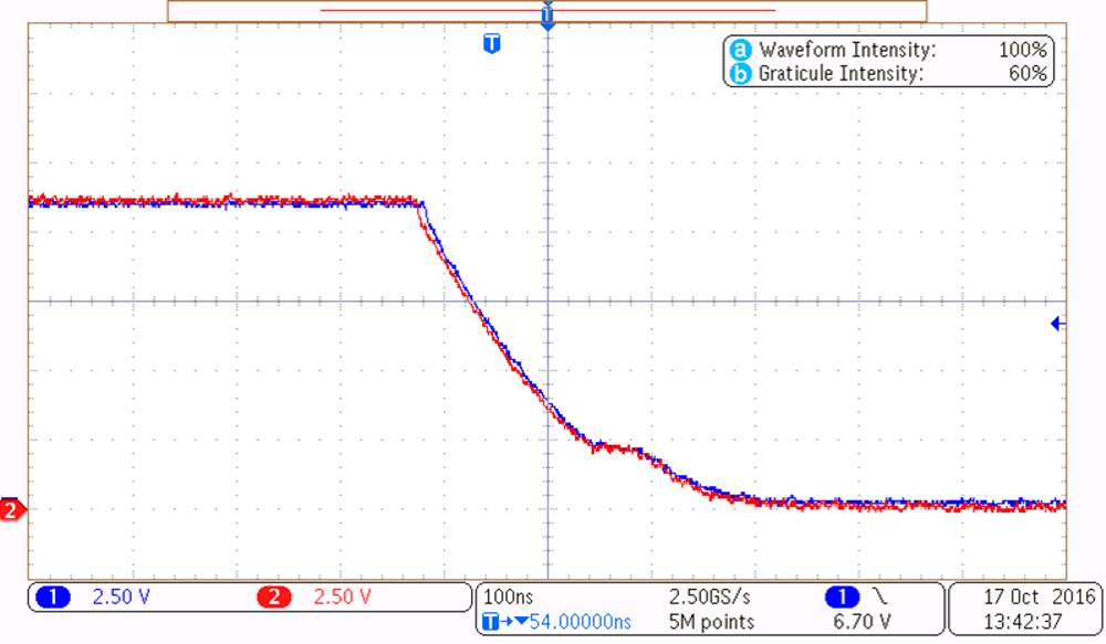
Waveforms from Figure 27 to Figure 30 show the skew in VGS when comparing the parallel FETs. The gate drive current per FET is set to a 340-mA source and a 1-A sink current. The current controlled gate driver and low parasitic in the gate driver circuit path helps in dynamic characteristics during switching and ensures proper dynamic current sharing. The 3.3-Ω external gate resistor is used to limit the circulation current between the gate source of paralleled FETs. If a single MOSFET is used, the external gate resistor is not required.
 Figure 27. Low-Side FET Turnon VGS
  Figure 29. High-Side FET Turnon VGS
  Figure 28. Low-Side FET Turnoff VGS
  Figure 30. High-side FET Turnoff VGS