TIDUCT9A January 2017 – March 2020
3.2.3.2.1 Overview
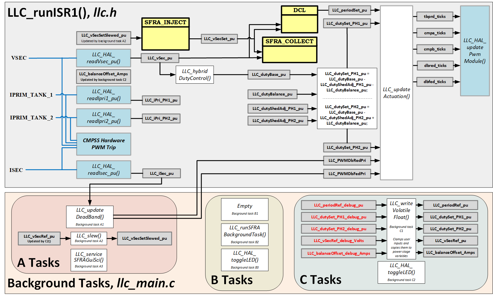
The software has been configured to provide closed loop voltage control for the two-phase, interleaved LLC resonant converter power stage. A two-pole, two-zero controller module (DCL_runDF22_C1) is used to implement the control law. The option for a PID controller module (DCL_runPID_C1) is also provided and can be selected from the powerSUITE GUI. The output voltage feedback LLC_vSec_pu is an input to the controller block. The reference input to the controller block comes from the slewed output voltage command LLC_vSecSet_pu. If used, the SFRA signal is applied to the voltage reference. The controller output LLC_periodSet_pu is used by the driver to update PWM registers similar to lab one. The output voltage command can be adjusted from the Expressions Window using the variable LLC_vSecRef_debug_Volts. The software block diagram is shown in Figure 27
 Figure 27. TIDM-1001 - Lab 2 Software Diagram
 Similar to lab one, on-chip analog comparators (selected in llc_user_settings.h file) and corresponding DAC mechanisms are used to provide overcurrent and overvoltage protection (for the TIDM-1001 board these are CMPSSs 1, 2, 3, and 4). The reference trip level for the comparators can be set using the powerSUITE GUI, which updates the LLC_IPRI1_TRIP_AMPS, LLC_IPRI2_TRIP_AMPS, LLC_ISEC_TRIP_AMPS, LLC_VSEC_TRIP_VOLTS defines in the LLC_settings.h file. The comparator output is configured to generate a one-shot trip action on the PWM modules, selected in llc_user_settings.h, whenever the sensed current or voltage is greater than the set limit. The flexibility of the trip mechanism on C2000 devices provides the possibility for taking different actions on different trip events. In this project all PWM outputs are driven low immediately on a comparator event to protect the power stage.
The converter is driven at a PWM switching frequency between 200 kHz and 350 kHz. The ISR is triggered by a spare PWM module (PWM3). This ISR is where the control code is executed.
Similar to lab one, a task state-machine has been implemented as part of the background code. Tasks are arranged in groups (A1, A2, A3…, B1, B2, B3…, C1, C2, C3…). Each group is executed according to three CPU timers, which are configured with periods of 1 ms, 20 ms, and 50 ms respectively. Within each group (for example, B) each task is run in a round-robin manner. For example, group B executes every 20 ms, and there are three tasks in group B. Therefore, B1, B2, and B3 execute once every 60 ms.