TIDUDG1 July   2022


  1.   Description
  2.   Resources
  3.   Features
  4.   Applications
  5.   5
  6. 1System Description
  7. 2System Overview
    1. 2.1 Block Diagram
    2. 2.2 Design Considerations
      1. 2.2.1 MIL-STD-1275E versus MIL-STD-1275D
      2. 2.2.2 Reverse Polarity Event
      3. 2.2.3 Voltage Spike Event
      4. 2.2.4 Voltage Spike Event: Component Selection
      5. 2.2.5 Voltage Surge Event
      6. 2.2.6 Voltage Surge Event: Component Selection
    3. 2.3 Highlighted Products
      1. 2.3.1 LM7480-Q1
      2. 2.3.2 LM5069
  8. 3Hardware, Testing Requirements and Test Results
    1. 3.1 Hardware Requirements
    2. 3.2 Test Setup
    3. 3.3 Test Results
  9. 4Design and Documentation Support
    1. 4.1 Design Files
      1. 4.1.1 Schematics
      2. 4.1.2 BOM
    2. 4.2 Documentation Support
    3. 4.3 Support Resources
    4. 4.4 Trademarks

Test Results

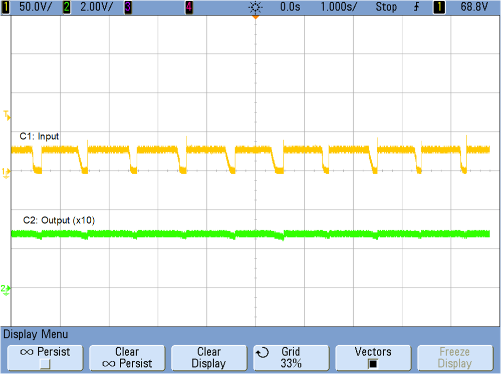
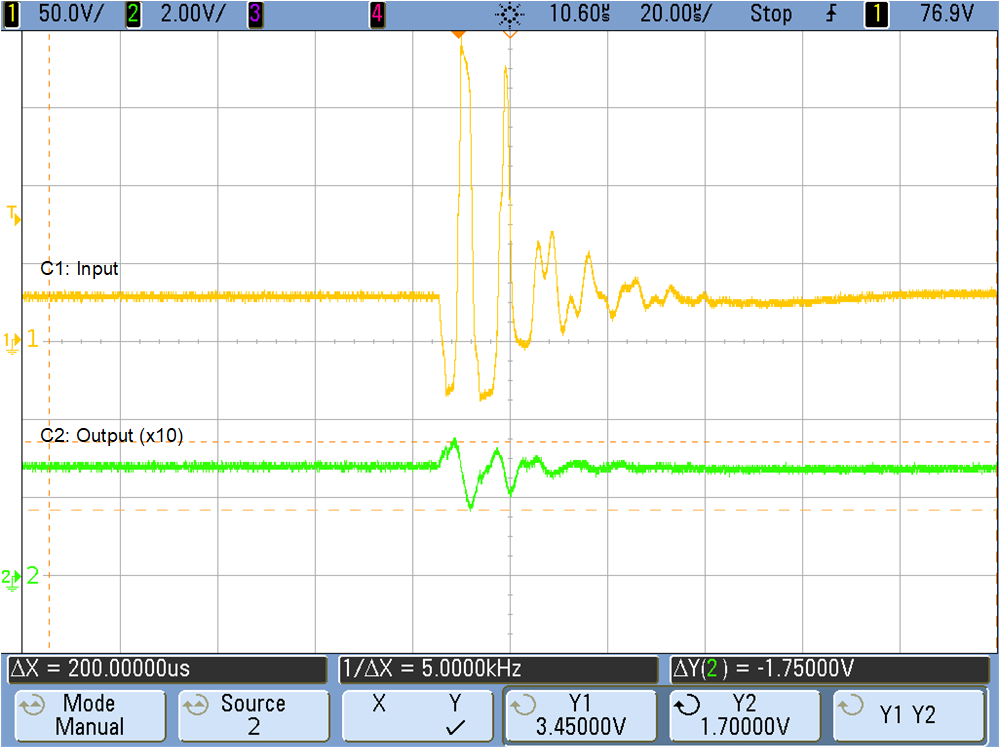
The following testing was done by NTS, and probed and captured by Texas Instruments.
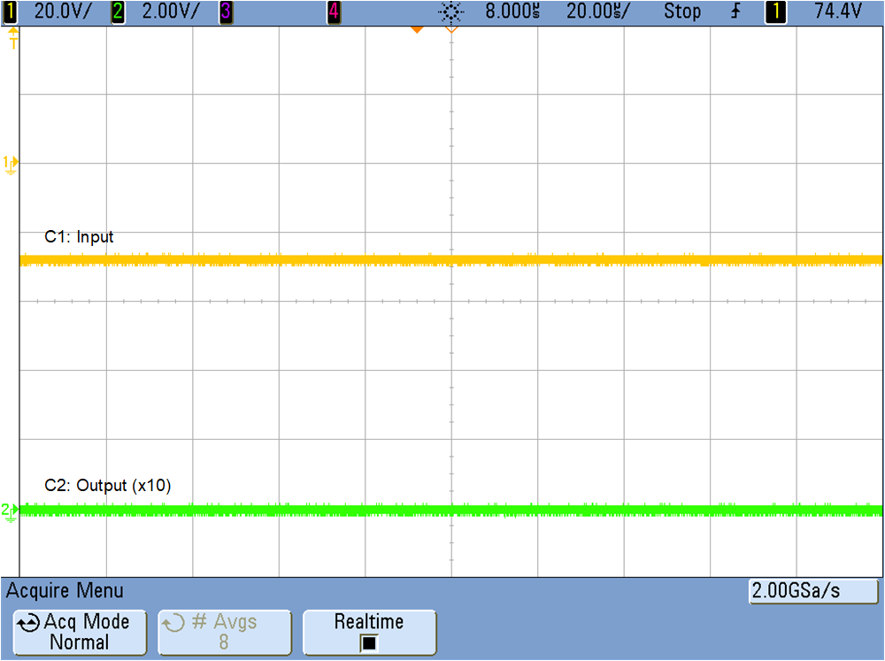
GUID-20220615-SS0I-KBQS-WXZZ-FZ2LTZ6JZH95-low.png Figure 3-5 Reverse Polarity Event
GUID-20220615-SS0I-BMFW-RXVQ-0KPQMMZ250R8-low.png Figure 3-6 Emitted Voltage Spike Event
GUID-20220615-SS0I-BRLQ-TRMD-BQGWJRTHGQGR-low.png Figure 3-7 +250-V Injected Voltage Spike
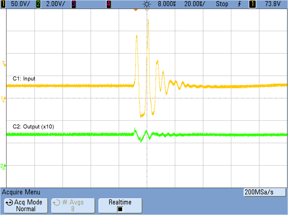
GUID-20220615-SS0I-4DQP-8DNP-MZZWMZZVTF3Z-low.png Figure 3-8 –250-V Injected Voltage Spike Event
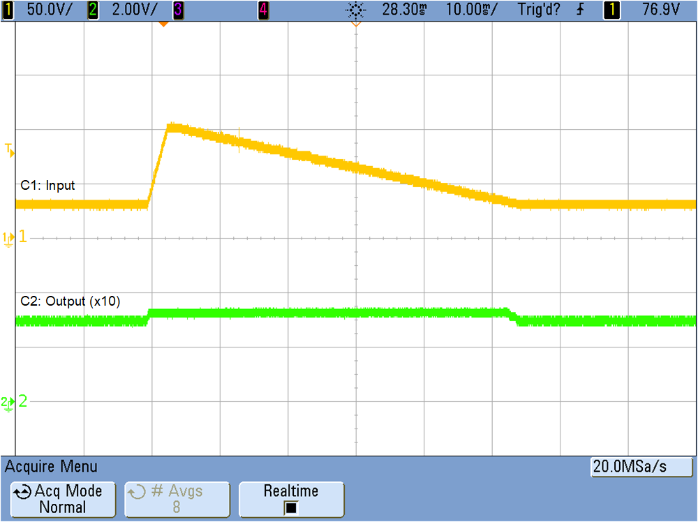
GUID-20220615-SS0I-WDQP-JH7G-QHV7LRSLQ85W-low.png Figure 3-9 100-V Surge Event: Low Current
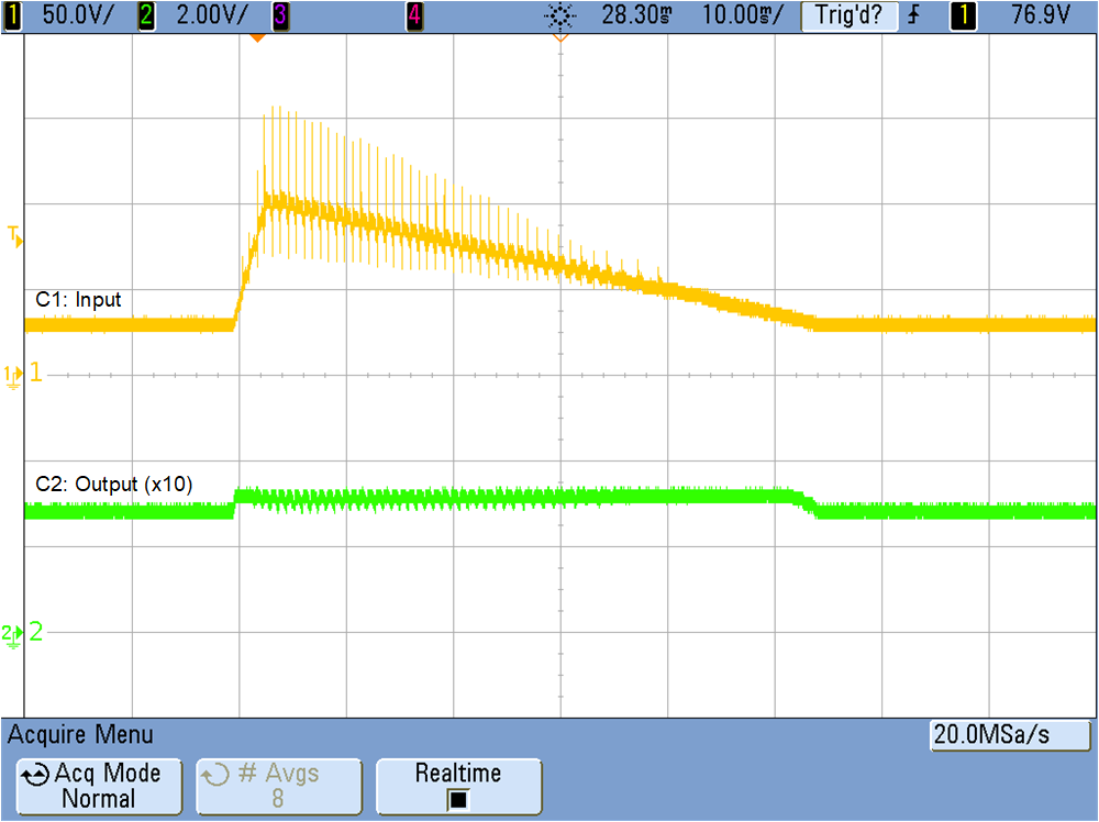
GUID-20220615-SS0I-TDX5-P1ZF-SC7F6WGPG6FF-low.png Figure 3-10 100-V Surge Event: 2-A Load
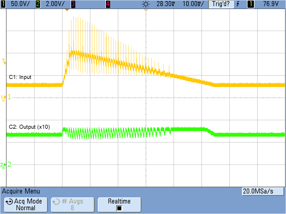
GUID-20220615-SS0I-NRWD-6ZKC-TX54K2C5D5DJ-low.png Figure 3-11 100-V Surge Event: 4-A Load