TIDUDG1 July 2022
3.1 Hardware Requirements
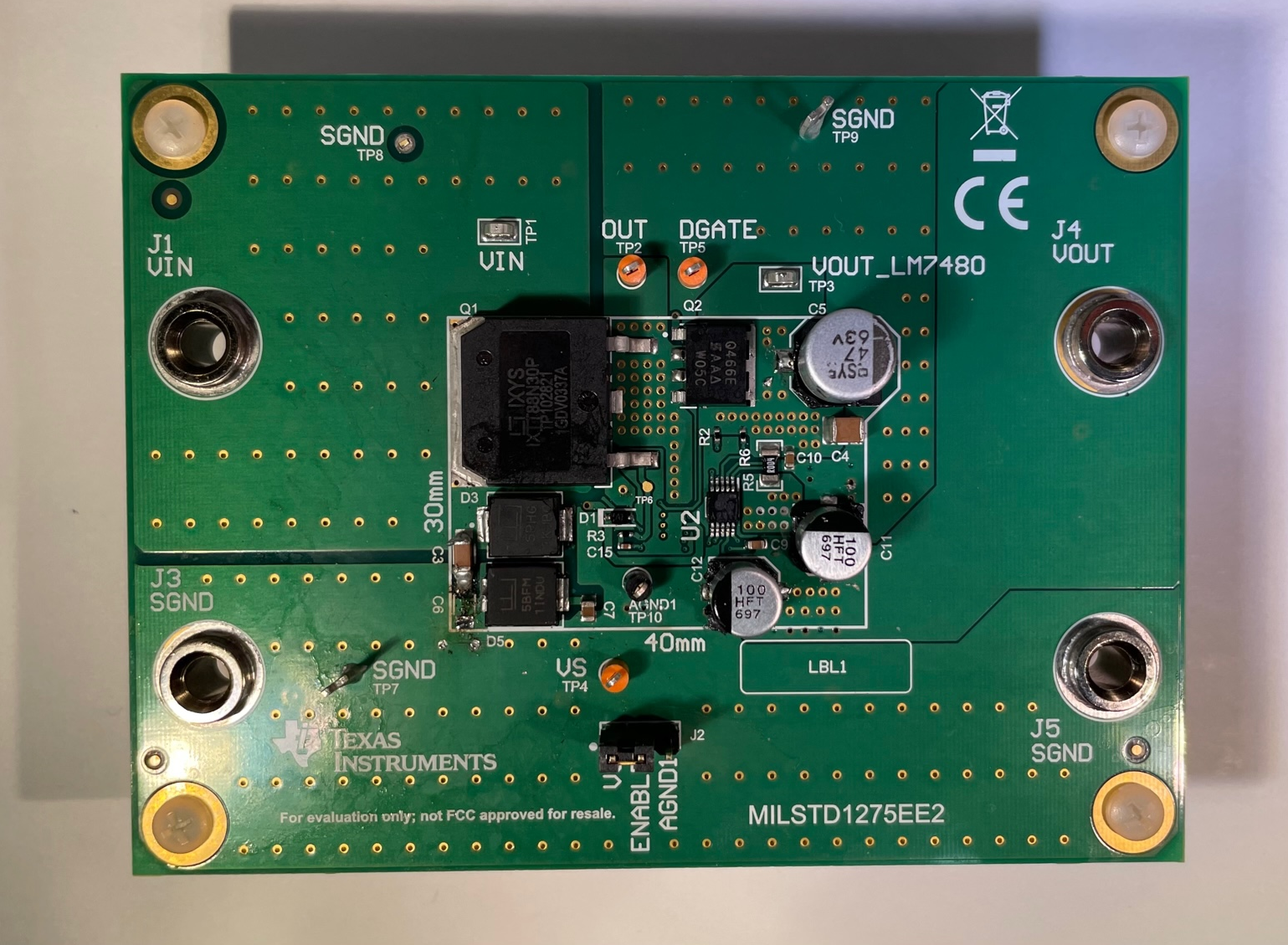
Figure 3-1 shows the TIDA-010242 board.
 Figure 3-1 MIL-STD-1275E board
This sections shows how to setup the TIDA-010242 for testing.
- Power Supply Input - Connect the input power to J1 and J3 (SGND). The nominal power supply is 28 V and put the current limit for the power supply at 5 A.
- Enable Jumper - Place a shunt across pin 1 and 2 of J2 to enable the device. A shunt across 2 and 3 or the shunt is DNP disables the LM7480-Q1.
- Power Output - The output power can be measured or connected to via J4 and J5 (SGND). These jumpers can also be used to connect to a electronic load for load testing.