TIDUDJ6B August 2022 – February 2023 OPA388-Q1
- Description
- Resources
- Features
- Applications
- 5
- 1System Description
- 2System Overview
- 3Hardware, Testing Requirements, and Test Results
- 4Design Files
- 5Software Files
- 6Related Documentation
- 7Trademarks
- 8Revision History
2.3.1 Isolation Leakage Current Theory
Isolation leakage measurements are typically performed in one of the subsystems in an HEV or EV system. Predicting the isolation breakage location is difficult and not possible to dousing isolated measurement techniques. The most effective way to measure isolated leakage current is by breaking the isolation of a complete system with a known resistance. If there is no current flowing between the switched path, then there is no parallel path which indicates that system is safe without any isolation breakages.
Designers must understand the type of failure and calculate the accurate isolation breakage parameters such as location (voltage) and resistance to classify the severity level. Isolation leakage resistance provides the information about the possible amount of leakage current for the second path, which can potentially electrocute the operator or passenger. To obtain a complete board diagnosis, break the isolation at two locations with known resistance paths.
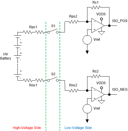
#T5081059-21 is one of the examples of isolation breakage measurements using this reference design. S1 and S2 are relays used to switch the measurement paths. Rps1 and Rps2 are resistors used in the high-resistance path from the positive line whereas Rns1 and Rns2 are resistors used in the negative line. Rs1 and Rs2 are the series resistors used for isolation current measurements. An inverting op-amp configuration with VREF (bias supply) is used for the measurements.
 Figure 2-6 HEV and EV Isolation
During normal conditions when S1 is closed, no leakage enters the circuit because there is no closed path. The ideal condition is to set the VREF potential at Rps1 and Rps2 with respect to chassis ground. ISO_POS must still stay at VREF voltage when S1 is closed. In a practical circuit based on the type of op amp, its input differential voltage, and bias currents, variations will occur in ISO_POS voltage measurements. The circuit behavior is similar when only S2 is closed, as shown in #T5081059-22.
 Figure 2-7 Normal Case: Only One Switch
Closed
Figure 2-7 Normal Case: Only One Switch
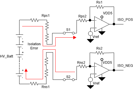
Closed#T5081059-23 shows that, if both switches are closed, leakage current from a high-voltage battery flows using the chassis ground of the HEV or EV. Select resistors Rps1, Rps2, Rns1, and Rns2 such that they have very low leakage current (< 1 mA) in the chassis ground for the maximum battery voltage.
 Figure 2-8 Normal Case: Both Switches Closed
As per #GUID-DAC72D72-4569-4827-9B2E-C3D75C8C43B2, the VREF and resistors are fixed. Measure the ISO_POS with a 16-bit or 12-bit analog-to-digital converter (ADC) for better precision and resolution. Compare the measured value of ISO_POS with the known parameters of HV battery voltage and resistors used in the design. System calculations must have accurate voltage measurements. If the calculated value is beyond the tolerance level of the system, then consider it to be isolation breakage in the system. To minimize the error in the system, it is important to select high-precision metal electrode leadless face (MELF) resistors and op amps with low offset and bias currents. The designer can measure the offset voltage of the opamp and calibrate it in the system. Calibrating the input bias currents of opamps is difficult and they greatly influence measurements of the isolation leakage currents.
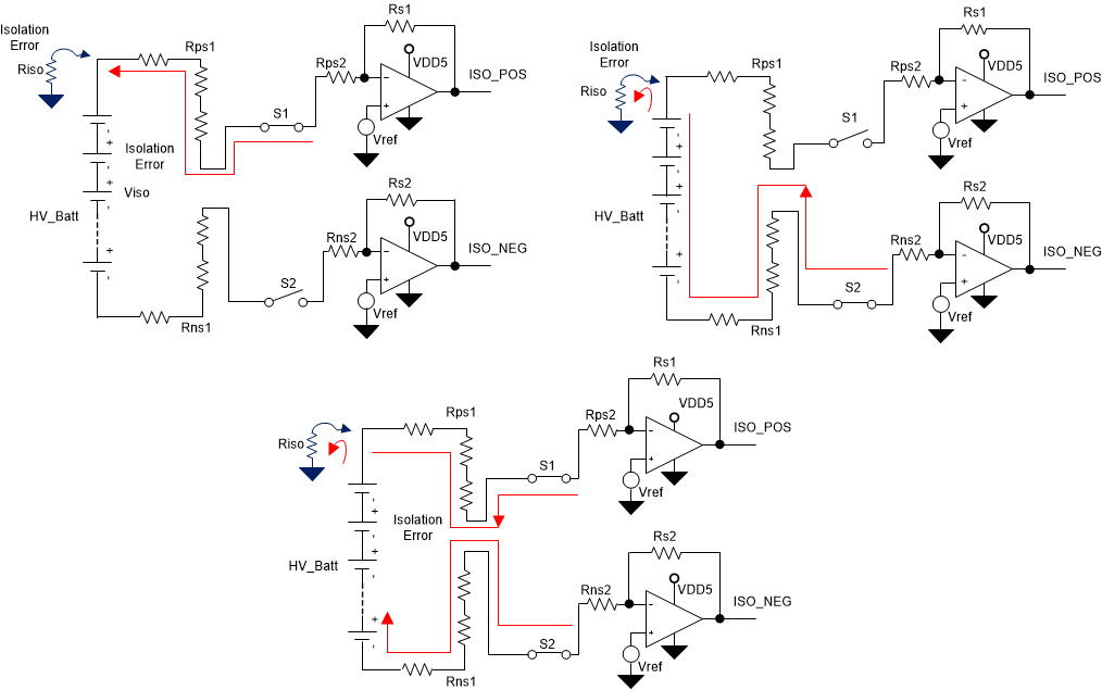
As stated in GUID-2D6D63A5-1DDB-458F-89C8-88F8DE79E9FE.html#GUID-2D6D63A5-1DDB-458F-89C8-88F8DE79E9FE, there are multiple root causes for the isolation breakage in the system. If the isolation breakage happens at the positive line of a high-voltage system, the circuit behavior is as shown in #T5081059-24. Riso is the isolation resistance from the high-voltage positive line to chassis ground, it can be as low as mΩ to MΩ. To perform the safety analysis, the designer must first identify the resistance of the isolation breakage and location. When only S1 is closed, there is no closed path for the high-voltage battery. Only leakage current flows from the low-voltage system due to the reference bias potential on the high-voltage line. The leakage current is negligible when only S1 is closed because the reference voltage is low (< 5 V) and the resistors are quite high (Rps1 + Rps2 > 500 kΩ).
 Figure 2-9 Isolation Error at Positive
When only S2 is closed, the high-voltage battery is in series with Rns1, Rns2, Riso, and VREF. A significant leakage current flows from the high-voltage section to the chassis ground based on the battery voltage, Rns1, and Rns2. This is the actual leakage current from high-voltage to chassis ground, which can be measured at ISO_NEG.
#T5081059-25 shows an equivalent circuit for isolation leakage current measurements when both S1 and S2 are closed. Considering that precision components are used in the circuit, input impedance, bias currents, and offset voltages of op amps are neglected.
 Figure 2-10 Equivalent Circuit for HV POS Isolation Leakage
Leakage currents in #T5081059-25 can be calculated by using the superposition of voltage sources. With the same reference supply and no offset voltage in the op amps, the leakage currents due to the VREF supply is negligible and canceled in the circuit (because of symmetry). HV_BATT is the significant voltage source which contributes to leakage current in the chassis ground. If Riso is too low, then the I_Leak2 current shown in #T5081059-25 will be negligible. The key contributor variable leakage currents are the HV_BATT power source and isolation resistance. The measurements of ISO_N are significant because they can be used to find the leakage currents and isolation resistance when an isolation error occurs at a high-voltage positive terminal.
A similar analysis of the leakage currents is valid with the error at a negative potential. A couple of equations will change, but most of the theory remains the same. Measurements of ISO_POS are significant when an isolation error at the negative terminal of the high-voltage battery exists.