TIDUDJ6B August 2022 – February 2023 OPA388-Q1
- Description
- Resources
- Features
- Applications
- 5
- 1System Description
- 2System Overview
- 3Hardware, Testing Requirements, and Test Results
- 4Design Files
- 5Software Files
- 6Related Documentation
- 7Trademarks
- 8Revision History
3.2.1 Test Setup
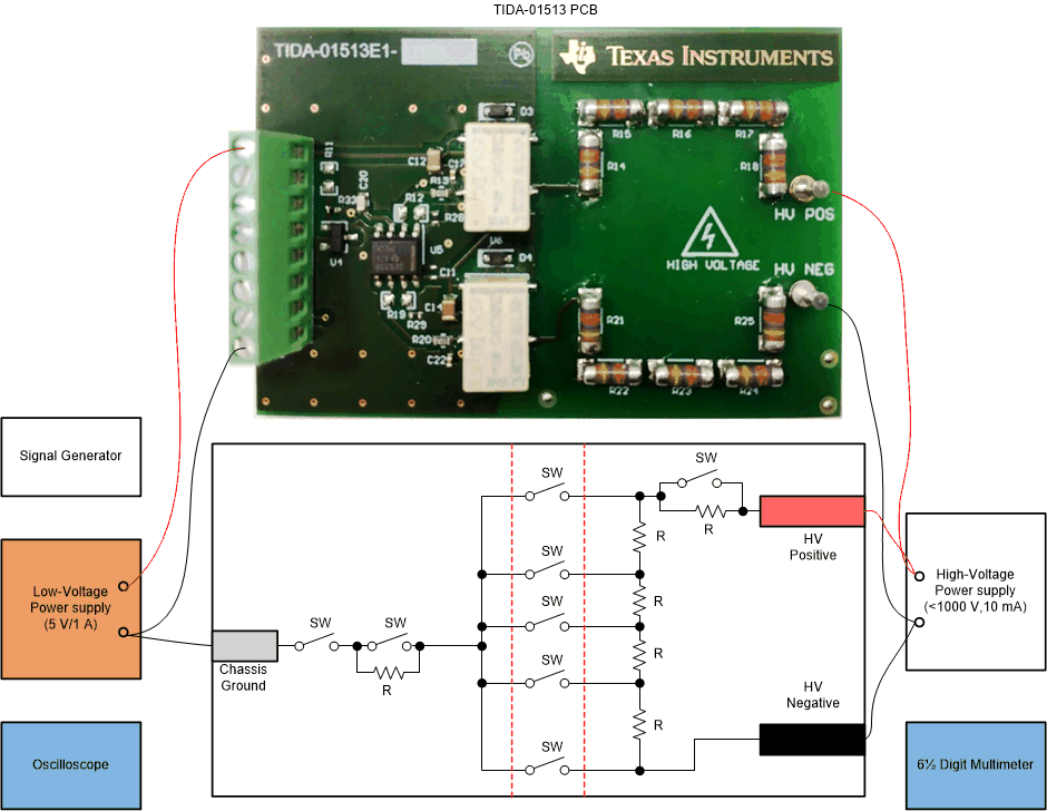
Be sure to take safety precautions as provided by a lab safety team when performing isolation breakage tests. The test setup must comply with regional safety norms. Connect the reference design to the load card, power supplies, and measurement equipment as shown in #T5081059-28. Use a signal generator to control the relays of the design board. If any one of the relays is closed, isolation is broken on the respective voltage divider (positive or negative potential divider) to support the isolation measurements. Set a constant low-voltage supply to 5 V as per the design. Use an oscilloscope to monitor the analog voltages of the reference design. As part of the measurements, some of the tests are done to calculate the errors. Use a 6½ digit multimeter (DMM) to support the same. Connect the high-voltage power supply to both the design and its load card. Perform measurements at different voltages and at multiple error points with variable resistance.
To measure isolation leakage currents, R1, R2, R3, R4, R5, and R6 of the design are not populated. R14, R15, R16, R17, and R18 are populated to have 1.2 MΩ. This same resistor chain is used for R21, R22, R23, R24, and R25 to maintain symmetry. 100-kΩ resistors are populated in the load card, which support as potential dividers from the high-voltage to low-voltage section.
Due to test facility limitations, some of the measurements are performed at low voltage and prorated data to high voltage. Functional behavior, isolation leakage currents for these tests are maintained intact with appropriate changes to resistors and power source.
 Figure 3-6 TIDA-01513 Test Setup