TIDUDO6B May 2019 – October 2020
- Description
- Resources
- Features
- Applications
- 5
- 1System Description
-
2System Overview
- 2.1 Block Diagram
- 2.2 Highlighted Products
- 2.3
System Design Theory and Design Considerations
- 2.3.1 AFE4900 and Power Supply
- 2.3.2 CC2640R2F Microcontroller
- 2.3.3 PPG Measurement
- 2.3.4 ECG Measurement
- 2.3.5 Selecting TX Supply (TX_SUP) Value for Driving LEDs
- 2.3.6 Generating TX Supply for Driving LEDs
- 2.3.7 Generating RX Supply for AFE4900
- 2.3.8 Generating I/O Supply
- 2.3.9 Battery Input and Reservoir Capacitors
- 2.3.10 Battery Life Calculations
- 2.3.11 External Memory
- 2.3.12 LED Indications
- 2.3.13 Connections Between Sensor Board and ECG Board
-
3Hardware, Software, Testing Requirements, and Test Results
- 3.1 Required Hardware and Software
- 3.2 Testing and Results
-
4Design Files
- 4.1 Schematics
- 4.2 Bill of Materials
- 4.3
PCB Layout Recommendations
- 4.3.1 Layout for Main Board
- 4.3.2 Connection From PDs to AFE
- 4.3.3 Connections From LEDs to AFE
- 4.3.4 Connections From ECG PADs to AFE
- 4.3.5 Connections Between BT and AFE
- 4.3.6 Connections Between BT Antenna and Chip
- 4.3.7 Boost Converter
- 4.3.8 Buck-Boost Converter
- 4.3.9 Layouts for PPG Sensor Boards
- 4.3.10 Layout for ECG Sensor Board
- 4.3.11 Layout Prints
- 4.4 Altium Project
- 4.5 Gerber Files
- 4.6 Assembly Drawings
- 5Software Files
- 6Related Documentation
- 7About the Authors
- Revision History
3.1.1.2 Difference Between PPG Sensor Boards
One PPG sensor board uses the SFH 7072 device from OSRAM. The default configuration for the PPG sensor board follows:
- LED1 (green1) of the SFH7072 = connected to TX4 of the AFE4900 device
- LED2 (green2) of the SFH7072 = not connected to the AFE4900 device
- LED3 (red) of the SFH7072 = connected to TX2 of the AFE4900 device
- LED4 (IR) of the SFH7072 = connected to TX3 of the AFE4900 device
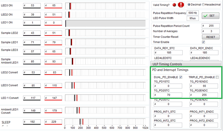
- The Dual_PD_Enable bit is set in the 0x4E register in the AFE4900 device (see Figure 3-7).
- PD1 of the AFE4900 device is connected to Broadband PD, and PD2 of the AFE4900 device is connected to Infrared-Cut PD.
Registers to be read for getting raw data follow:
- 0x2A – Raw PPG data from the red LED
- 0x2B – Raw PPG data from the IR LED
- 0x2C – Raw PPG data from the green LED
- 0x2D – Raw ECG data
 Figure 3-7 Timing and Settings for SFH 7072 PPG Sensor
The other PPG sensor board uses the OCS112 device from tBPC. The default configuration for the PPG sensor board follows:
- LED1 (red) of the OCS112 device = connected to TX2 of the AFE4900 device
- LED2 (IR) of the OCS112 device = connected to TX3 of the AFE4900 device
- LED3 (green) of the OCS112 device = connected to TX4 of the AFE4900 device
Because this sensor has only one PD, the Dual_PD_Enable bit is not set in the 0x4E register in the AFE4900 device (see Figure 3-8). PD1 of the AFE4900 device is always connected to PD of the sensor.
Registers to be read for getting raw data follow:
- 0x2A – Raw PPG data from the red LED
- 0x2B – Raw PPG data from the IR LED
- 0x2C – Raw PPG data from the green LED
- 0x2D - Raw ECG data
 Figure 3-8 Timing and Settings for OCS112 PPG Sensor
Note:
Figure 3-7 and Figure 3-8 are screen shots from the AFE4900EVM GUI (available at AFE4900EVM).