TIDUE73A April 2018 – November 2024
- 1
- Description
- Resources
- Features
- Applications
- 6
- 1System Description
- 2System Overview
- 3Hardware, Software, Testing Requirements, and Test Results
- 4Design Files
- 5Software Files
- 6Related Documentation
- 7Terminology
- 8About the Authors
- 9Revision History
1 System Description
Industrial drives, like servo drives, require accurate, highly-reliable, and low-latency position feedback. The BiSS protocol is designed for serial transfer of digital data between a sensor and a controller. BiSS stands for bidirectional serial synchronous. The BiSS interface was introduced by iC-Haus GmbH as an open-source protocol in 2002. BiSS-C mode is the continuous mode in which the BiSS-C interface reads out the position data cyclically.
The TIDM-1010 design implements a BiSS-C interface to a C2000 LaunchPad. BiSS-C is a pure serial, digital interface, based on the RS-485 standard. BiSS is capable of transmitting position values, along with other physical quantities, and allows reading and writing of the internal memory of the encoder. The transmitted-data types include absolute position, turns, temperature, parameters, and diagnostics. Figure 1-1 shows the major hardware blocks used in this design.
 Figure 1-1 TIDM-1010 Hardware Blocks and
Connectors
Figure 1-1 TIDM-1010 Hardware Blocks and
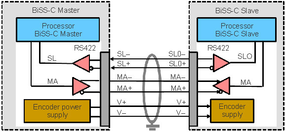
ConnectorsTIDM-1010 supports a point-to-point configuration which is typically used with the BiSS position or rotary encoders. The point-to-point topology is shown in Figure 1-2. In the point-to-point configuration, only one device with one or more sensors is operated on by the master. PM_bissc library only supports this configuration.
 Figure 1-2 BiSS-C Point-to-Point
Structure
Figure 1-2 BiSS-C Point-to-Point
StructureThe absolute position encoder connects to the TIDM-1010 through a 6-wire, shielded, cable. RS-485 is used as the physical layer. The 6 wires are:
- MA+ and MA-: Encoder clock (BiSS Master Clock) differential signals
- SL+ and SL-: Return data from the encoder (BiSS Slave return) differential signals
- V+ and V-: Power and ground supply for the encoder
The BiSS-C MA-clock frequency is variable and depends on the cable length (see Section 3.3.4). Depending on the encoder and the encoder cable, the maximum cable length or the maximum achievable clock frequency can vary. Because the quality of the cable has an impact on the communication performance, encoder manufacturers define these limits in their data sheets and recommend an appropriate cable for use with their encoders. More details of the protocol and point-to-point configuration can be found at BiSS Interface: BiSS User Society and Internet Platform.
The Texas Instruments C2000 Position Manager BiSS-C (PM_bissc) encoder interface enables a BiSS implementation without external hardware such as an FPGA or CPLD. The reference implementation features:
- Up to a 10 MHz clock frequency with a 10 m cable length
- Integrated cable-propagation delay-compensation
- Software driver functions:
- Perform a transaction with the encoder. This consists of sending the MA signal to the encoder and receiving the response.
- Calculate a CRC
- Compare the CRC received with the calculated CRC
- Unpacking the response data
This reference implementation includes all of the source code. Any changes needed for the implementation can be made by users as required by their application.
- Single-cycle-data (position + error + warning + CRC) transaction
- Single register read access
- Single register write access