TIDUE73A April 2018 – November 2024
- 1
- Description
- Resources
- Features
- Applications
- 6
- 1System Description
- 2System Overview
- 3Hardware, Software, Testing Requirements, and Test Results
- 4Design Files
- 5Software Files
- 6Related Documentation
- 7Terminology
- 8About the Authors
- 9Revision History
2.3.3 TIDM-1010 Board Implementation
The TIDM-1010 board provides the following:
- Differential line driver and receiver for RS-485 communication between a C2000 MCU and the encoder.
- TxEN signal routed from the MCU to the direction control of the RS-485 driver/receiver. For the BiSS-C implementation, this signal is held low.
- SPICLK signal routed to a GPIO where it can be controlled by the CLB peripheral. This connection is optional for all supported devices except the F2837xD, F2837xS and F28007x devices. On other devices, the CLB is capable of clocking the SPI peripheral within the device itself.
-
Note: The TIDM-1010 board is identical to the Position Manager BoosterPack (BOOSTXL-POSMGR), which means the TIDM-1010 board can interface with several other position encoder types. The board is fully populated by default for future compatibility. This reference design focuses on the BiSS-C, and the hardware blocks not mentioned in this document can be ignored.
Table 2-2 lists the connectors on the TIDM-1010 BiSS-C implementation and the functions of these connectors.
Table 2-2 TIDM-1010 Board and BOOSTXL-POSMGR Connectors
| CONNECTOR | DESCRIPTION | USED BY TIDM-1010 |
|---|---|---|
| Abs-Enc-1 (J7) | BiSS-C and other absolute encoders | Yes, LaunchPad Site 2 |
| Abs-Enc-2 (J8) | BiSS-C and other absolute encoders | No |
| Abs-Enc-2 Breakout (J10) | Allows two absolute encoders at site two using jumpers | No |
| SinCos (J14) | SinCos encoder | No |
| Resolver (J14 and J15) | Resolver interface with 15-V excitation circuitry | No |
| PTO (J17) | Pulse-train output | No |
| J1, J3 and J4, J2 | BoosterPack connector | Yes |
| J6 | 5-V DC supply input | Yes |
| J16 | 15-V DC resolver excitation input | No |
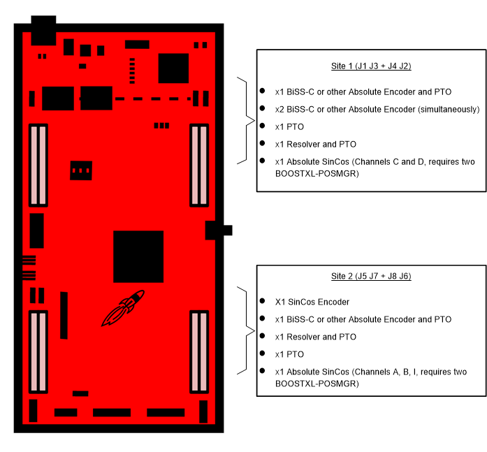
Figure 2-8 describes the encoder support at each site of the LaunchPad development kit.
 Figure 2-8 TIDM-1010 Board and BOOSTXL-POSMGR Encoder Support
As provided, TIDM-1010 uses LaunchPad Site 2 and BOOSTXL-POSMGR's Encoder 1 connections. Figure 2-9 shows the connections. The complete schematic of the TIDM-1010 BoosterPack can be downloaded from the BOOSTXL-POSMGR product page.
 Figure 2-9 BoosterPack Block Diagram