TIDUE73A April 2018 – November 2024
- 1
- Description
- Resources
- Features
- Applications
- 6
- 1System Description
- 2System Overview
- 3Hardware, Software, Testing Requirements, and Test Results
- 4Design Files
- 5Software Files
- 6Related Documentation
- 7Terminology
- 8About the Authors
- 9Revision History
3.3.1 Hardware Configuration
- Make sure that the jumper configuration of the TIDM-1010 device is as described in Table 3-1.
- Connect the TIDM-1010 device to the LaunchPad using
the BoosterPack site-two connector (J1, J3 and J4, J2). Make sure the TIDM-1010
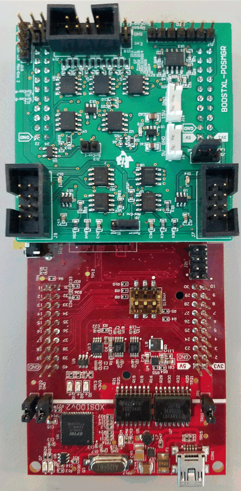
device is connected to site two of the LaunchPad, as shown in Figure 3-4.
 Figure 3-4 TIDM-1010 Board
Connected to Site Two of LaunchPad™
 - Connect the USB cable to the LaunchPad.
- Connect to the encoder:
- Prepare an adapter to connect the cable to the BiSS-C interface using the circular female to wire the leads adapter (see the BOM for the header used for the encoder connector, J7).
- Connect CLK+/CLK- to the BiSS-C MA+/MA- signal of the encoder.
- Connect DATA+/DATA- to the encoder's response SL+/SL-.
- Insert the header of the adapter created in the
previous step to connect to Abs-Enc-1 (J7). The female end of the cable
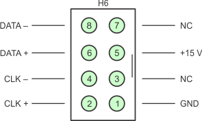
connects to the encoder. Figure 3-5 shows the pinout of J7.
 Figure 3-5 Abs-Enc-1 (J7)
Pinout on TIDM-1010 Board
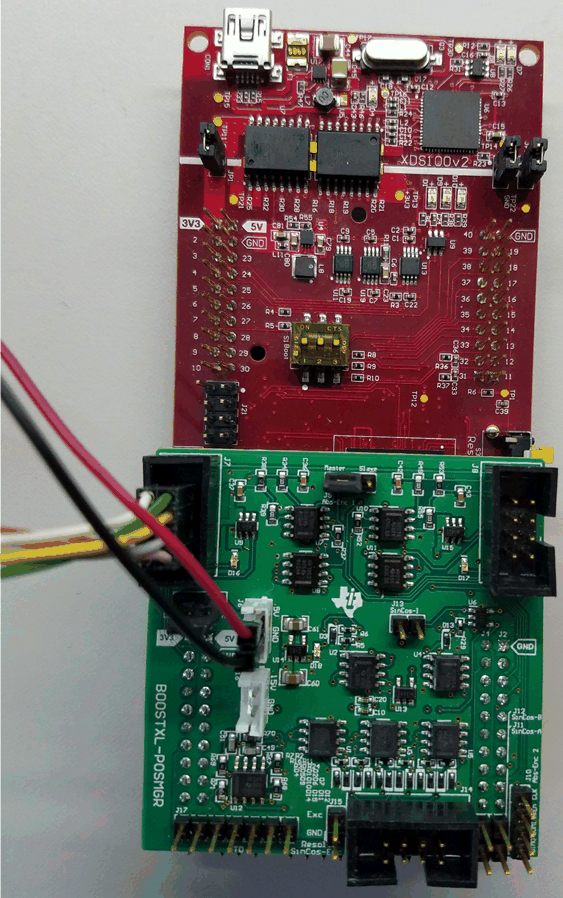
- Supply 5-V DC and GND to J6, as shown in Figure 3-1. The board now looks like Figure 3-6. BoosterPack LED D18 turns on, which shows that the board has power. Note: For some encoders the BoosterPack may not provide an adequate current at power up. If the encoder fails to respond, try connecting a power supply external to the BoosterPack to the encoder. If this is done, connect a common ground to the BoosterPack.
 Figure 3-6 TIDM-1010 Board
Connected to BiSS-C Encoder