TIDUEA0A March 2019 – September 2020
- 1
- Description
- Resources
- Features
- Applications
- 6
- 1System Description
- 2System Overview
-
3Hardware, Software, Testing Requirements, and Test Results
- 3.1 Required Hardware and Software
- 3.2
Testing and Results
- 3.2.1 Test Setup for Performance Testing
- 3.2.2 EMI and EMC Test Requirements for DRTD
- 3.2.3 TMP117 EMI/EMC Test Results
- 3.2.4 TMP117 Based Temperature Probe Measurement Performance Test Results
- 3.2.5 TMP116 Based Temperature Probe Measurement Performance Test Results
- 3.2.6 I2C-bus Cable Length Considerations
- 3.2.7 Power Supply
- 3.2.8 ESD Test Results for TMP116
- 3.2.9 Summary
- 4Design Files
- 5Software Files
- 6Related Documentation
- 7About the Author
- 8Revision History
3.2.3 TMP117 EMI/EMC Test Results
The TMP117 has been tested using the requirements as per the standards summarized above. Table 3-2 below illustrates the results of the testing. As you can see, the TMP117 passes all of the listed standards. This design showcases the setup and subsequent results obtained when preforming the test as per IEC61000-4-3.
|
Test Number |
Standard |
Environment Class |
Number of Samples |
Result |
|---|---|---|---|---|
|
1 |
EN 61000 4-2 Electrostatic discharge, Contact |
A,C |
2 |
Pass |
| EN 61000 4-2 Electrostatic discharge, Air |
A,C |
2 |
Pass |
|
|
2 |
EN 61000-4-3 Electromagnetic field |
A |
2 |
Pass |
| EN 61000-4-3 Electromagnetic field |
C |
2 |
Pass |
|
| EN 61000-4-3 Electromagnetic field specifically caused by digital radio equipment |
A |
2 |
Pass |
|
| EN 61000-4-3 Electromagnetic field specifically caused by digital radio equipment |
C |
2 |
Pass |
|
|
3 |
EN 61000-4-4 Fast transients (bursts) |
A,C |
2 |
Pass |
|
4 |
EN 61000-4-5 |
A,C |
1 |
Pass |
|
5 |
EN 61000-4-6 |
A |
2 |
Pass |
| EN 61000-4-6 |
C |
2 |
Pass |
|
|
6 |
EN 61000-4-8 |
A |
2 |
Pass |
| EN 61000-4-8 |
C |
2 |
Pass |
|
|
7 |
EN 55022 Conducted emission on signal and power DC lines |
A,C |
2 |
Pass |
|
8 |
EN 55022 |
A,C |
2 |
Pass |
|
Environment Class |
A |
B |
C |
|---|---|---|---|
|
Frequency Range |
26 MHz–1000 MHz |
||
|
Test Level |
3 V / m |
3 V / m |
10 V / m |
|
Modulation |
AM (1KHz) 80% |
||
|
Environment Class |
A |
B |
C |
|---|---|---|---|
|
Frequency Range |
800 MHz–960 MHz 1850 MHz–2700 MHz |
||
|
Test Level |
10 V / m |
10 V / m |
30 V / m |
|
Modulation |
AM (1 KHz) 80% |
||
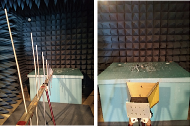
Figure 3-4 shows the physical test setup and Figure 3-3 shows the schematic. The TMP117 was tested for frequencies listed in EN-1434 with isolated I2C using digital isolators and shielded copper cables. Dwell time was 30 seconds with frequency steps of 1 MHz. No communication errors or abrupt change in temperature measurement was observed. No sudden change in temperature measurement was observed after removing the field.
 Figure 3-3 EN 61000-4-3 Test Setup
Diagram.
  Figure 3-4 EN 61000-4-3 Setup Inside the
Chamber.