TIDUED6B august 2018 – april 2023
- Description
- Resources
- Features
- Applications
- Design Images
- 1System Description
- 2System Overview
- 3Hardware, Software, Testing Requirements, and Test Results
- 4Design Files
- 5Software Files
- 6Related Documentation
- 7Trademarks
- 8About the Author
- 9Revision History
3.2.1.1 People Counting Setup
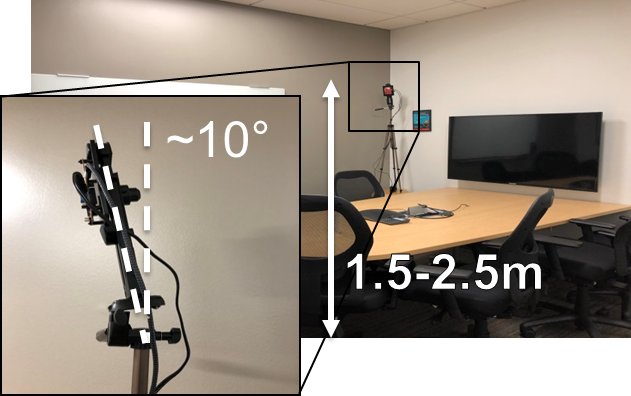
For best results, the sensor node should be positioned high enough to be above the top of tracked objects and with a slight down tilt. The aim is to position the sensor node so that the antenna beam can encompass the area of interest. If the down tilt is too severe, noise from ground clutter increases and the effective sensing area decreases. If there is no down tilt, counting performance would be worse for cases in which one person is in line with and shielded by another person. Given the antenna radiation pattern of the sensor node, consideration should be taken to not mount the sensor node too close or oriented with the beam directed to the ceiling as this can increase the noise floor and result in less optimal performance.
 Figure 3-19 Sensor Node (IWR6843 + CC1352) Setup
Setup Requirements:
- Elevate Sensor Node 1.5–2.5 m high
- Down tilt: approximately 10 degrees
Setup using suggested tripod and smartphone clamp mount:
- Screw on clamp mount to tripod
- Clamp the sensor node across its width below the power barrel jack to attach sensor node.
- Adjust the tripod head for approximately 10 degree downward tilt (Tip: Bubble or level smartphone applications can be used to measure down tilt)
- Plug in the 5-V power supply to the sensor node
- Extend the tripod so that the sensor node is elevated 1.5–2.5 m from the ground
- Position the sensor node and tripod assembly in the desired location of room. The sensor node should be positioned so that the 120 degree FOV of the radar antenna encompasses the area of interest and points to the region in which people are expected to enter the space.
 Figure 3-20 Setup with Clamp Mount