TIDUED6B august 2018 – april 2023
- Description
- Resources
- Features
- Applications
- Design Images
- 1System Description
- 2System Overview
- 3Hardware, Software, Testing Requirements, and Test Results
- 4Design Files
- 5Software Files
- 6Related Documentation
- 7Trademarks
- 8About the Author
- 9Revision History
3.1.2.2 Loading the IWR6843 Firmware
This reference design was tested with and includes the binary image for the 68xx People Counting demo included in the mmWave Sensors Industrial Toolbox v. 3.2.0.
Follow these steps to load the IWR6843 firmware:
Note:
Make sure the CC1352 LaunchPad is not attached to the MMWAVEICBOOST board.
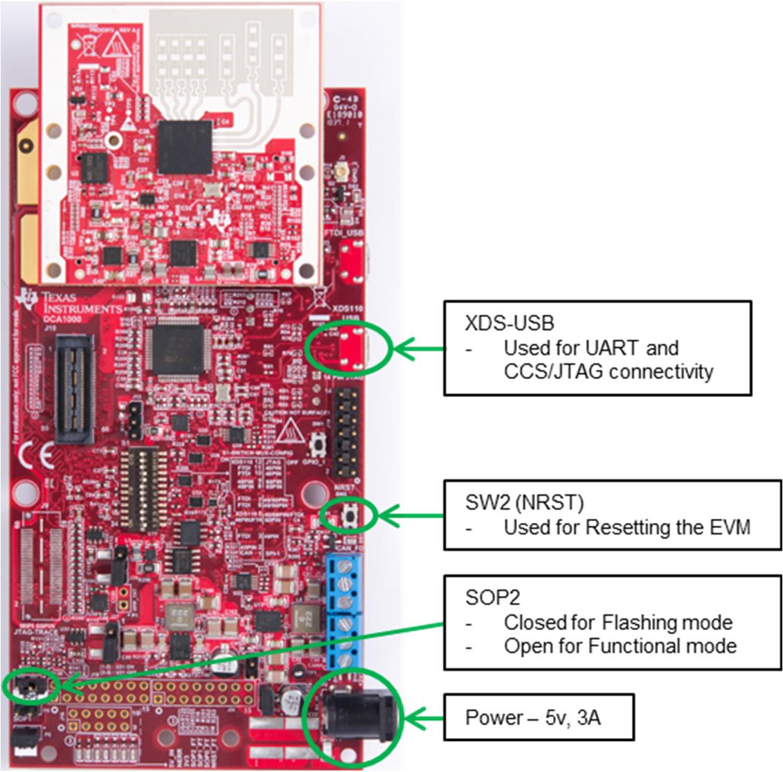
- Connect the IWR6843ISK and MMWAVEICBOOST boards together as shown in Figure 3-7.
- Plug in micro-USB cable and 5-V power supply to mmWave boards as shown in Figure 3-7.
 Figure 3-7 IWR6843ISK and MMWAVEICBOOST Boards
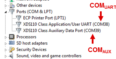
 - Connect the mini-USB cable to your PC and check the COM ports in Windows Device Manager. Figure 3-8 shows how the mmWave setup exports two virtual COM ports:
- XDS110 Class Application/User UART (COMUART): Used for passing configuration data and firmware to the mmWave boards.
- XDS110 Class Auxiliary Data Port (COMAUX): Used to send processed radar data output.
 Figure 3-8 COM Port Identification
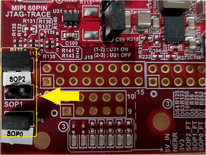
- Put the MMWAVEICBOOST in flashing mode by connecting jumpers on SOP0 and SOP2 as shown in Figure 3-9. Then reset the MMWAVEICBOOST with SW2.
 Figure 3-9 SOP0 and SOP2 Location
 - Download and open http://www.ti.com/tool/UNIFLASH.
- In the New Configuration section, locate and select IWR6843 ES1.0.
- Click Start to proceed.
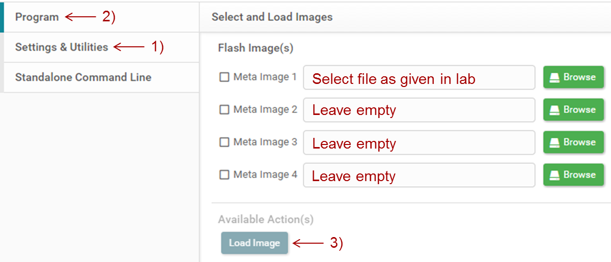
- Click the Settings & Utilities tab. Under setup, fill the COM Port text box with the Application/User UART COM port number (COM UART) noted earlier.
- In the Program tab, browse and locate the PC_lab_xwr68xx.bin file from the TIDA-010022 firmware folder.
 Figure 3-10 Loading Image
- Reset the board with SW2 and click on Load Image.
- Successful Flash Procedure: The UniFlash console should indicate: [SUCCESS] Program Load completed successfully
- Power off the board and remove only the SOP2 jumper.
- Make sure SOP2 has been removed and that the IWR6843 boards are power cycled. This puts the boards back in functional mode.