TIDUED7A November 2018 – November 2022
2.3.2 Input Protection
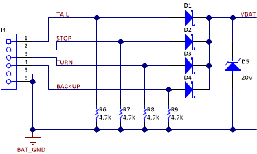
In this reference design, reverse polarity protection is implemented by using Schottky diodes D1 through D4 on the input power lines as shown in Figure 2-5. The diodes are acting as an OR-ing circuit, which provides power to the pre-voltage regulator if one or more power rails get active.
For transient protection, a transient voltage suppressor (TVS) diode D5 is placed at the input after the reverse polarity protection to clamp the voltage. However, the LM5155-Q1 supports up to 45-V input voltage.
Resistors R6 through R9 are placed to sink reverse current of the Schottky diodes.
 Figure 2-5 Schematic Input Protection