TIDUEE5A October   2018  – May 2022


  1.   Description
  2.   Resources
  3.   Features
  4.   Applications
  5.   5
  6. 1System Description
    1. 1.1 Key System Specifications
  7. 2System Overview
    1. 2.1 Block Diagrams
    2. 2.2 Design Considerations
    3. 2.3 Highlighted Products
      1. 2.3.1 DLP3030-Q1
      2. 2.3.2 DLPC120-Q1
      3. 2.3.3 TMS320F28023
    4. 2.4 System Design Theory
      1. 2.4.1 Head-up Display Parameter Design and Tradeoffs
        1. 2.4.1.1 Field of View and Eyebox
        2. 2.4.1.2 Resolution
        3. 2.4.1.3 Virtual Image Distance
      2. 2.4.2 Picture Generation Unit Design Decisions
        1. 2.4.2.1 Etendue Efficiency Match
        2. 2.4.2.2 Aperture Size: Selecting f/# of Optics
        3. 2.4.2.3 Thermal Design
        4. 2.4.2.4 LED Selection Summary
      3. 2.4.3 Design Summary
  8. 3Hardware, Software, Testing Requirements, and Test Results
    1. 3.1 Required Hardware and Software
      1. 3.1.1 Hardware
      2. 3.1.2 Software
    2. 3.2 Testing and Results
      1. 3.2.1 Test Setup
      2. 3.2.2 Test Results
  9. 4Design Files
    1. 4.1 Schematics
    2. 4.2 Bill of Materials
    3. 4.3 PCB Layout Recommendations
      1. 4.3.1 Layout Prints
    4. 4.4 Cadence Project
    5. 4.5 Gerber Files
    6. 4.6 Assembly Drawings
  10. 5Software Files
  11. 6Related Documentation
    1. 6.1 Trademarks
  12. 7Terminology
  13. 8Revision History

LED Selection Summary

Figure 2-9 shows that despite emitting more lumens, larger LEDs do not necessarily offer more system lumens. This example uses Osram’s Q8WP and CSL LEDs which are readily available for the automotive market today. For a PGU that requires 55 lumens, CSL LEDs with an f/2.6 aperture provide more than the required brightness at the best power efficiency.
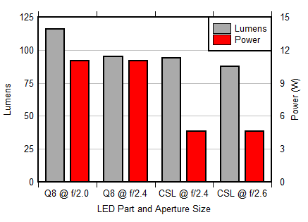
GUID-C3314156-4850-4C98-B31A-6A6FE701029C-low.gifFigure 2-9 Brightness vs Power With Different LEDs and f/#