TIDUEE5A October 2018 – May 2022
- Description
- Resources
- Features
- Applications
- 5
- 1System Description
- 2System Overview
- 3Hardware, Software, Testing Requirements, and Test Results
- 4Design Files
- 5Software Files
- 6Related Documentation
- 7Terminology
- 8Revision History
2.4.1.1 Field of View and Eyebox
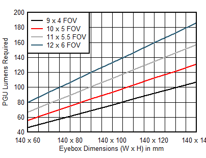
An AR HUD system has many design parameters. While all system parameters are important, there are two system parameters that are most responsible for determining PGU requirements in a HUD system: FOV and eyebox size. The following sections describe the high level tradeoffs associated with HUD FOV and eyebox size.
FOV in a HUD system is the solid angle of the displayed image, measured from the center of the eyebox. Typical FOV ranges from 4° × 2° in a small, conventional HUD up to greater than 12° × 6° in a large AR HUD. A larger FOV increases the size of the image seen by the driver. To achieve a larger eyebox, the HUD design must use a PGU with a higher luminous output to maintain the same brightness image. The DLP3030-Q1, combined with an LED based optical system, can output up to 90 lumens at room temperature and over 60 lumens across the entire automotive qualified operating temperature range (–40°C to 105°C).
Eyebox is the area at the viewing plane where the displayed image is visible to the driver. Typical eyebox sizes range from 100 mm × 60 mm to much larger 140 mm × 140 mm. A larger eyebox allows the driver to move their head further from center and use different seat positions while maintaining visibility of the displayed image. A large vertical eyebox also allows drivers of different heights to accurately see the image without adjusting any internal HUD components like mirrors. Because a larger eyebox spreads the image light out more than a smaller eyebox, larger eyeboxes require a higher lumen PGU to achieve the same brightness image.
Figure 2-3 provides an estimated PGU brightness requirement to achieve 15,000 nits (cd/m2) for given eyebox and FOV specifications. For an eyebox size of 140 mm × 60 mm with a 10° × 5° FOV, approximately 55 lumens are required from the PGU.
 Figure 2-3 PGU Lumens vs Eyebox Dimensions and Field of View