TIDUEM5 December   2018


  1.    Description
  2.    Resources
  3.    Features
  4.    Applications
  5.    Design Images
  6. 1System Description
    1. 1.1 Key System Specifications
    2. 1.2 Introduction
    3. 1.3 MSP430FR2633 CapTIvate MCU
  7. 2System Overview
    1. 2.1 Block Diagram
    2. 2.2 Design Considerations
    3. 2.3 Highlighted Products
      1. 2.3.1 MSP430FR2633 MCU Block Diagram
      2. 2.3.2 CapTIvate Technology Block Diagram
  8. 3Hardware, Software, Testing Requirements, and Test Results
    1. 3.1 System Design Theory
    2. 3.2 Capacitive Touch Sensors
      1. 3.2.1 Wheel Sensor
      2. 3.2.2 Slider Sensor
      3. 3.2.3 Button Sensor
    3. 3.3 Gesture and Key Mapping
      1. 3.3.1 Media Player
      2. 3.3.2 USB HID Keyboard Data
    4. 3.4 Capacitive Touch Gestures
      1. 3.4.1 How Gesture Detection Works
      2. 3.4.2 Tap Gesture
      3. 3.4.3 Double-Tap Gesture
      4. 3.4.4 Tap-and-Hold Gesture
      5. 3.4.5 Swipe Gesture
      6. 3.4.6 Slide Gesture
    5. 3.5 Getting Started With Hardware
    6. 3.6 Getting Started With Firmware
      1. 3.6.1 Programming Target MCU
      2. 3.6.2 MSP430FR2633 CapTIvate Gesture Firmware
      3. 3.6.3 Memory Footprint
      4. 3.6.4 MSP430F5529 HID Keyboard Device Firmware
    7. 3.7 Testing
      1. 3.7.1 Gesture
      2. 3.7.2 Power Measurements
      3. 3.7.3 Moisture Tolerance
  9. 4Demonstration
    1. 4.1 Wheel
      1. 4.1.1 Volume Control
      2. 4.1.2 Changing Music Tracks
        1. 4.1.2.1 Play/Pause
      3. 4.1.3 Mute
    2. 4.2 Slider
      1. 4.2.1 Volume Control
      2. 4.2.2 Changing Music Tracks
      3. 4.2.3 Play or Pause
      4. 4.2.4 Mute
    3. 4.3 Buttons
      1. 4.3.1 Volume Control
      2. 4.3.2 Changing Music Tracks
      3. 4.3.3 Play or Pause
      4. 4.3.4 Mute
  10. 5Design Files
    1. 5.1 Schematic
    2. 5.2 Bill of Materials
  11. 6Software Files
  12. 7Related Documentation
    1. 7.1 Trademarks
  13. 8Terminology
  14. 9About the Author

Wheel Sensor

A capacitive touch wheel sensor is constructed as a circular copper pattern on the PCB containing 3 or 4 interdigitated sensing elements. The interdigitation provides a high resolution, linear output as the finger moves around the wheel . A wheel's basic functionality reports a finger position anywhere on the sensor. By adding some gesturing intelligence to the firmware, both finger direction and speed can also be derived.

Specific regions or zones on the wheel's surface can be defined or mapped in software creating a flexible user-interface that allows various application functions to be controlled depending where the wheel is touched. Incorporating motion gesture features, such as Slide or Swipe, adds another level of user action possibilities. Figure 4 shows some of the possible gesture features that could be used for controlling the functionality on a wireless smart speaker.
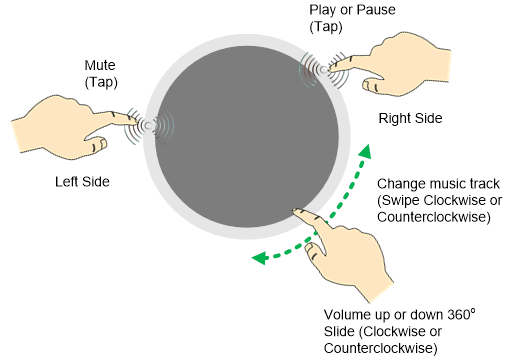
TIDM-02004 tidm-02004-wheel-gesture.gifFigure 4. Wheel Sensor Gesture Examples

One additional benefit of the capacitive touch wheel is the ability to re-purpose the wheel interface hardware design from product to product and change only features or functionality as needed in firmware.