TIDUEM7A April 2019 – February 2021
- Description
- Resources
- Features
- Applications
- 5
- 1System Description
-
2System Overview
- 2.1 Block Diagram
- 2.2 Highlighted Products
- 2.3 Design Considerations
- 2.4
Hardware, Software, Testing Requirements, and Test Results
- 2.4.1 Required Hardware and Software
- 2.4.2
Testing and Results
- 2.4.2.1 Test Setup
- 2.4.2.2 Test Results
- 3Design Files
- 4Related Documentation
- 5About the Author
- 6Revision History
2.3.2.2.2 MCU Procedure for Entering and Exiting Current-Detection Mode
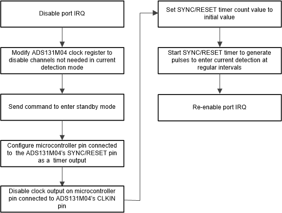
Figure 2-10 shows an example procedure that can be followed by the host MCU to trigger the ADS131M04 device to enter current-detection mode. An example time the ADS131M04 device can be selected to enter current-detection mode is when there is an early indication that the input voltage to the power supply is dropping, which may indicate either a power outage or the neutral removal from the meter. In this design, this mode triggered using the power fail indication on the TPS7A78 device.
 Figure 2-10 Example Procedure for Entering Current-Detection Mode
In this example procedure, the port interrupt associated with the ADS131M04 DRDY pin assertion is disabled so that the device can be properly configured without the software being triggered to read ADC samples. After disabling the port interrupt, the host MCU can modify one of the ADS131M04 registers to disable all the channels that a comparison should not be done on for current-detection mode. Namely, disable all of the voltage channels and potentially one of the two current channels. Subsequently, the host MCU should send a command to the ADS131M04 for it to enter standby mode. After sending the command to enter standby mode, the MCU pin connected to the SYNC/ RESET pin of the ADS131M04 device can be configured using the port mapping controller to be a timer output instead of a regular GPIO pin. Disable the clock from the MCU to the CLKIN pin of the ADS131M04 device to reduce current consumption since this external clock is not needed for standby mode or current-detection mode. In addition, initialize the counter on the timer that is used to generate the SYNC/ RESET pulse so that there will not be a long wait before the MSP432 MCU first provides the pulse to the ADS131M04 to enter current-detection mode. After the timer count is initialized, the timer is then started, which provides the pulses on the ADS131M04 SYNC/ RESET pin to start current-detection mode at regular intervals, as mentioned in the previous section. At this point, any time DRDY is asserted low indicates that tamper current has been detected so the DRDY port interrupt is re-enabled to capture this. The host MCU can then be put in a low-power mode (note that for this design specifically the MCU was not put in a low power mode). If tamper current has been detected, the DRDY assertion causes an interrupt to the MCU, which wakes the MCU up, if it is in a low-power mode.
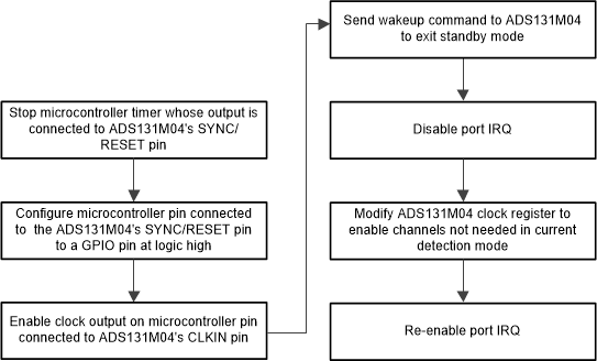
Figure 2-11 shows an example process for exiting current-detection mode. An example when this can be triggered is when power has been restored to the electricity meter after the end of a power outage. For this design, this event is triggered by the power good signal of the TPS7A78 device being asserted.
 Figure 2-11 Example Procedure for Exiting Current-Detection Mode
This example process for exiting current-detection mode first begins by the MCU exiting any low power mode that the device may have been put in during the power outage. Next, the timer that was used to provide the pulses on the SYNC/ RESET pin is disabled. The GPIO pin of the MCU that was connected to the ADS131M04 SYNC/ RESET pin can be configured back to GPIO operation in case it is desired to reset the ADS131M04 manually later. Next, the clock from the MCU to the CLKIN pin of the ADS131M04 device is enabled again. After enabling the clock, a wake-up command is sent from the host MCU to the ADS131M04 device so that it can exit standby mode and go back to continuous conversion mode. At this point, the device is now converting so the DRDY pin is asserted at a regular rate. Samples are not read at this point because some of the channels may have been disabled from before current-detection mode was entered. The port interrupt associated with DRDY is specifically disabled so that samples are not read yet. Next, one of the ADS131M04 registers is modified so that all of the ADC channels are enabled again. After enabling all the channels, the port interrupt is enabled again so that ADC values can start getting read again. At this point, the normal sampling process from before current-detection mode was entered has been resumed.