TIDUEM7A April 2019 – February 2021
- Description
- Resources
- Features
- Applications
- 5
- 1System Description
-
2System Overview
- 2.1 Block Diagram
- 2.2 Highlighted Products
- 2.3 Design Considerations
- 2.4
Hardware, Software, Testing Requirements, and Test Results
- 2.4.1 Required Hardware and Software
- 2.4.2
Testing and Results
- 2.4.2.1 Test Setup
- 2.4.2.2 Test Results
- 3Design Files
- 4Related Documentation
- 5About the Author
- 6Revision History
2.4.2.1.3 Current-Detection Mode Testing
For testing current-detection mode, the trigger current on the line and neutral channel was tested as well as the average current consumption of the ADS131M04 device. These tests were performed using the register settings mentioned in Section 2.3.2.3.1.7.
Before performing trigger current testing, the ADS131M04 offset registers are used to subtract the average ADC offset on the shunt and CT current channels. This is necessary because the shunt and CT current channels have different PGA gain settings(PGA gain=1 for CT and PGA gain=32 for shunt). At these different gains, the channels would have a difference in ADC offset so offset calibration was performed to provide better matching between the two current channels, which is necessary to get consistent results between the two channels using only one threshold value. Based on the test settings, the ADS131M04 is then placed in current detection. After placing the device in current-detection mode, the input current is varied from 50 mA to 10 A on the shunt channel(while no current is on the CT channel) to see at which current would the ADS131M04 start indicating to the MSP432 MCU of tampering. This first current is logged in the test results. A similar test is done on the CT channel as well to determine its triggering current in current-detection mode.
Two sets of current-detection current-consumption tests were performed in this design. For both tests, the ADS131M04 and the rest of the board are powered separately with the two power supplies sharing the same ground connection. The ADS131M04 was powered at 3.3 V by the N6705 power analyzer, which plots the average current consumption of the ADS131M04. The rest of the board was powered at 3.3 V from a regular power supply.
In the first test, the current consumption of the ADS131M04 is measured during current-detection mode for different combinations of enabled channels. The number of channels used in current-detection mode affects the current consumption of the device in this mode. In addition, for the scenario where current-detection mode is enabled for two channels, the pairings of enabled channels can also affect the current consumption. There is shared circuitry between channels 0 and 1 as well as between channels 2 and 3 that are on if one of the two channels in these pairs are enabled. As a result, the lowest current consumption is expected for the two-enabled channel case when channels 0 and 1 are enabled or when channels 2 and 3 are enabled. In this design, channels 1 and 2 are used for the current channel so these two channels are the two channels that are potentially enabled in current-detection mode; however, a lower current consumption is expected if the design was modified to use channels 0 and 1 for the current and channel 2 for voltage since the shared circuitry for channels 3 and 4 could be turned off in current-detection mode.
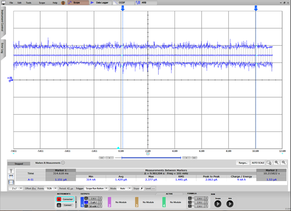
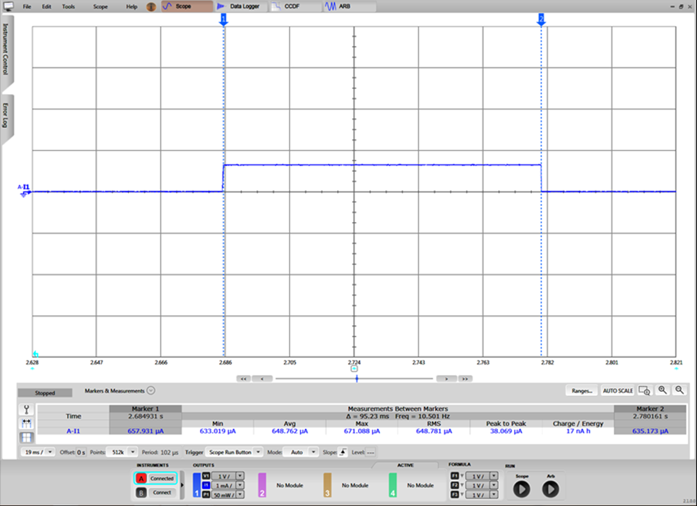
For the second current consumption test, the average current consumption was measured when current-detection mode is entered once every 10 seconds (tCD_mode_period = 10) and once every 64 seconds (tCD_mode_period = 64). Current-detection mode is enabled in the shunt (channel 1) and CT (channel 2) channels for this test. In this test, the ADS131M04 alternates between standby mode and current-detection mode. Since the current consumption in standby mode and current-detection mode are significantly different, the standby mode current consumption and current-detection mode current-consumption had to be taken separately using two different current range settings on the N6705 power analyzer. Figure 2-27 shows an example reading for standby mode, where an average current of 1.429 µA is measured. The duration the device is in current-detection mode is estimated by measuring the current consumption positive pulse width. Figure 2-28 shows an example reading for current-detection mode, where an average current of 648.762 µA and a current-detection duration of 95.23 ms are measured. Using this estimated current-detection duration, the average current during the estimated current-detection duration, and the average standby mode current consumption, the total average current consumption value across time is estimated. This average current consumption test was performed on three separate boards and averaged together for the total average current consumption test results shown in this design. The estimated current-detection duration and average standby mode current from this test was also used to estimate the average current consumption for the different combinations of enabled channels used in the first current-detection current-consumption test.
 Figure 2-27 Example Standby Mode Current Consumption Reading
 Figure 2-28 Example Current-Detection Mode Current Consumption Reading