TIDUEO1B April 2021 – June 2021
- Description
- Resources
- Features
- Applications
- 5
- 1General Texas Instruments High Voltage Evaluation (TI HV EVM) User Safety Guidelines
- 2System Description
- 3System Overview
-
4Hardware, Software, Testing Requirements, and Test Results
- 4.1 Required Hardware and Software
- 5Design and Documentation Support
- 6Terminology
- 7About the Author
- 8Revision History
4.1.2.1 Software Control Flow
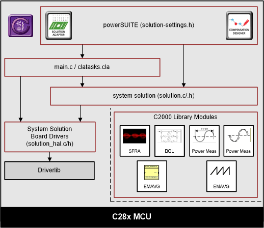
 Figure 4-3 Project Structure Overview
Solution specific and device independent files are <solution>.c/h. Board-specific and device-specific files are <solution>_hal.c/h. The main.c file of the project consists of the main function of the C project as well as ISR framework and calls routines in other files. <solution>_settings.h and <solution>_user_settings.h consist of all the settings required for the solution.
<solution>_user_settings.h For this design, <solution> is psfbpcmc.
<solution>_clatask.cla file include the CLA Task definitions.
The powerSUITE page can be opened by clicking the main.syscfg file, listed below the project explorer.
The powerSUITE page generates the <solution>_settings.h file. This file is the only file used in the compile of the project that is generated by the powerSUITE page. The user must not modify this file manually, as the changes will be overwritten by powerSUITE each time the project is rebuilt. The changes will only happen after rebuilding the entire project TheKit.json and solution.js files are used internally by the powerSUITE and must also not be modified by the user. Any changes to these files will result in the project not functioning properly.
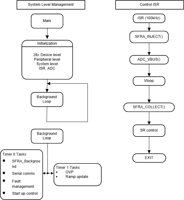
 Figure 4-4 PCMC Software Flow
In Figure 4-4, the project consists of an interrupt service routine, which is called every PWM cycle, called ISR1(), where the control algorithm is executed. In addition to this, there are background tasks, which are called in a polling fashion and can be used to run slow tasks for which absolute timing accuracy is not required.
The system is controlled by two feedback loops; an outer voltage loop, implemented using software control block, and an inner peak current loop, implemented using the on-chip analog comparator, DAC and PWM hardware resources. The voltage loop controller is executed at a rate of 100 kHz (same as the PWM frequency).