TIDUES0E June 2019 – April 2024 TMS320F28P550SJ , TMS320F28P559SJ-Q1
- 1
- Description
- Resources
- Features
- Applications
- 6
- 1System Description
- 2System Overview
- 3Circuit Description
- 4Hardware, Software, Testing Requirements, and Test Results
- 5Design Files
- 6Related Documentation
- 7Terminology
- 8About the Author
- 9Revision History
2.3.4.4 Phase Shift
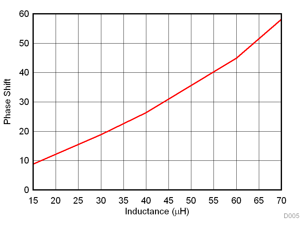
The phase shift of the converter is dependent on the value leakage inductor. The phase shift for required power transfer is given by Equation 16.
 Figure 2-18 Variation of Phase Shift With
Leakage Inductance
Figure 2-18 Variation of Phase Shift With
Leakage InductanceFigure 2-18 shows the required phase shift in degrees over leakage inductance for V1 = 800 V, V2 = 500 V, N = 1.6, FS= 100 kHz, and Pout= 10 kW. The graph illustrates that for a small value of inductance, a maximum power transfer at a small value of phase shift is obtained. To have fine control over power transferred, fine high-resolution steps in which the phase can be varied must be obtained. Alternatively, a larger inductor can obtain maximum power transfer at a high value of phase shift for better control. For the selected L = 35 µH, a phase shift of 23 degrees or 0.4 radians is required.