TIDUET0A November   2019  – July 2020


  1.   Description
  2.   Resources
  3.   Features
  4.   Applications
  5.   5
  6. 1System Description
    1. 1.1 Key System Specifications
  7. 2System Overview
    1. 2.1 Block Diagram
    2. 2.2 Design Considerations
    3. 2.3 Highlighted Products
      1. 2.3.1 TPS61088-Q1
      2. 2.3.2 LMR33630-Q1
      3. 2.3.3 TPS7A2501
      4. 2.3.4 ATL431AIBDZR
    4. 2.4 System Design Theory
  8. 3Hardware, Software, Testing Requirements, and Test Results
    1. 3.1 Required Hardware and Software
      1. 3.1.1 Hardware
    2. 3.2 Testing and Results
      1. 3.2.1 Test Setup
      2. 3.2.2 Test Results
  9. 4Design Files
    1. 4.1 Schematics
    2. 4.2 Bill of Materials
    3. 4.3 PCB Layout Recommendations
      1. 4.3.1 Layout Prints
    4. 4.4 Altium Project
    5. 4.5 Gerber Files
    6. 4.6 Assembly Drawings
  10. 5Related Documentation
    1. 5.1 Trademarks
    2. 5.2 Third-Party Products Disclaimer
  11. 6About the Author
  12. 7Revision History

Block Diagram

Figure 2-1 shows the block diagram of TIDA-050031. The output voltage of the buck converter is set at 9 V. The backup battery is charged by this 9 V voltage through the linear charger. After the main battery voltage drops low and the buck converter LMR33630-Q1 browns out, the linear charger stops working. The backup battery supplies the energy for the ECall system through the boost converter TPS61088-Q1.
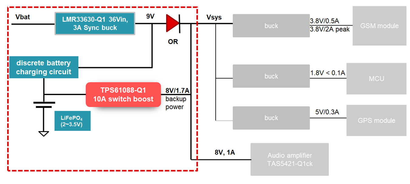
GUID-4D5FDA44-35F8-4ECC-884F-FAB79363C8BD-low.pngFigure 2-1 TIDA-050031 Block Diagram