TIDUET3 February   2021


  1.   1
  2.   2
  3.   3
  4.   4
  5.   5
  6.   6
    1.     7
  7.   8
    1.     9
    2.     10
    3.     11
      1.      12
      2.      13
      3.      14
      4.      15
      5.      16
      6.      17
      7.      18
      8.      19
      9.      20
    4.     21
      1.      22
        1.       23
        2.       24
        3.       25
        4.       26
        5.       27
        6.       28
        7.       29
        8.       30
      2.      31
        1.       32
        2.       33
        3.       34
        4.       35
        5.       36
        6.       37
        7.       38
        8.       39
        9.       40
        10.       41
        11.       42
        12.       43
  8.   44
    1.     45
      1.      46
    2.     47
      1.      48
        1.       49
      2.      50
        1.       51
          1.        52
          2.        53
        2.       54
          1.        55
          2.        56
          3.        57
          4.        58
          5.        59
          6.        60
          7.        61
  9.   62
    1.     63
      1.      64
      2.      65
      3.      66
      4.      67
      5.      68
    2.     69
    3.     70
    4.     71
    5.     72
  10.   73

Select LM/LR Ratio (LN) and QE

LN is the ratio between the magnetizing inductance and the resonant inductance.

Equation 26.
GUID-20210112-CA0I-0DPC-7HLK-5MHDJVK6TZNB-low.gif

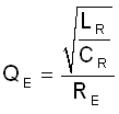
QE is the quality factor of the resonant tank.

Equation 27.
GUID-20210112-CA0I-6NCX-H3QW-C9SBL98L9JXL-low.gif

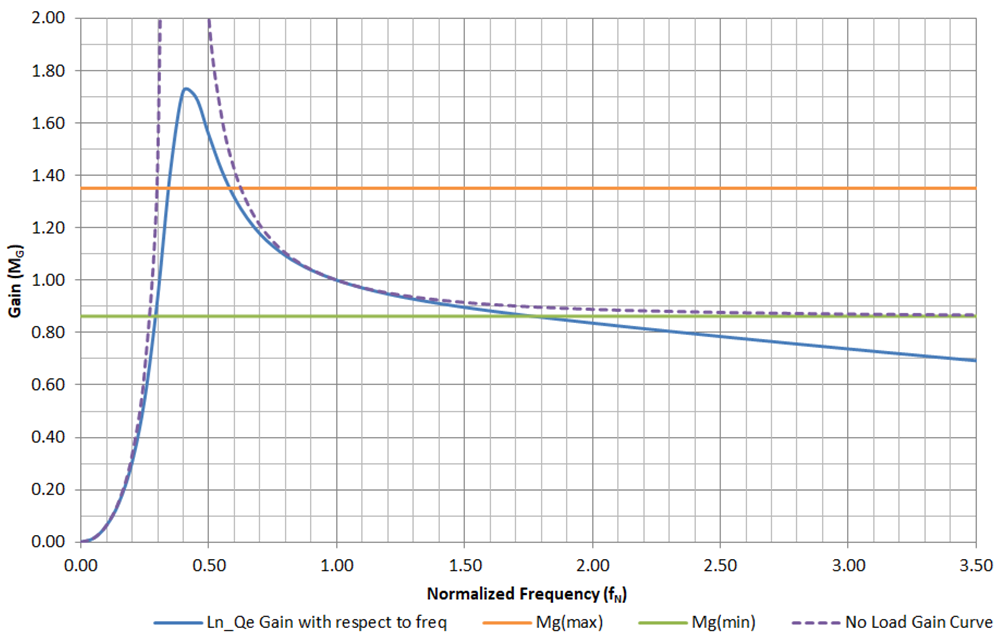
Selecting LN and QE values must result in an LLC gain curve, as shown in Figure 2-2, that intersects with

Mgmin and Mgmax traces. The peak gain of the resulting curve must be larger than Mgmax.

GUID-20210113-CA0I-HWVB-2TS4-226L8HBCFHF8-low.png

Figure 2-2 LLC Gain Curve for Selected LN and QE

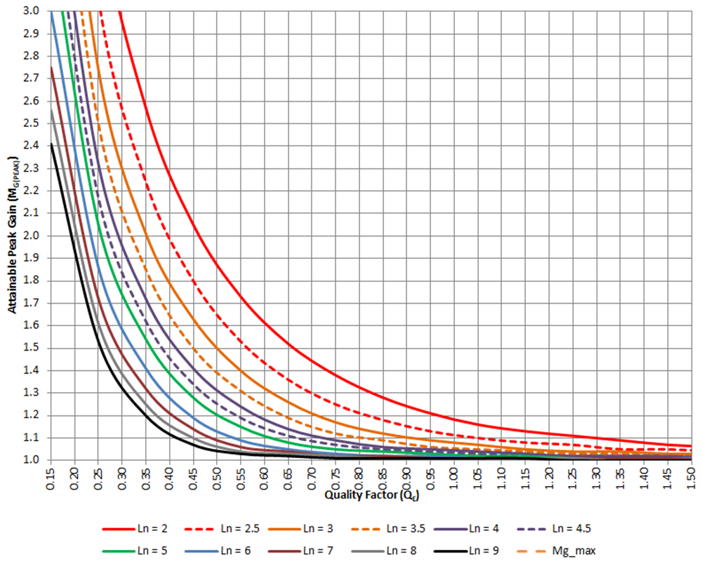
The relationship between MGpeak and QE with respect to LN is shown in Figure 2-3:

GUID-20210113-CA0I-PJCK-VBDH-3C4SN0LCRJP4-low.png

Figure 2-3 MGpeak and QE With Respect to LN