TIDUEW7 May 2020
- Description
- Resources
- Features
- Applications
- Design Images
- 1System Description
-
2System Overview
- 2.1 Block Diagram
- 2.2 Design Considerations
- 2.3 Highlighted Products
- 2.4 System Design Theory
- 3Getting Started, Testing Setup, and Test Results
- 4Design Files
- 5Software Files
- 6Related Documentation
3.1.2.1 Booting of TIDA-050043
Insert the SD card into the SD card slot provided in the board and set the boot switches to boot from SD card. If executables are not found in the configured boot source, then the software is automatically fetched from the SD card.
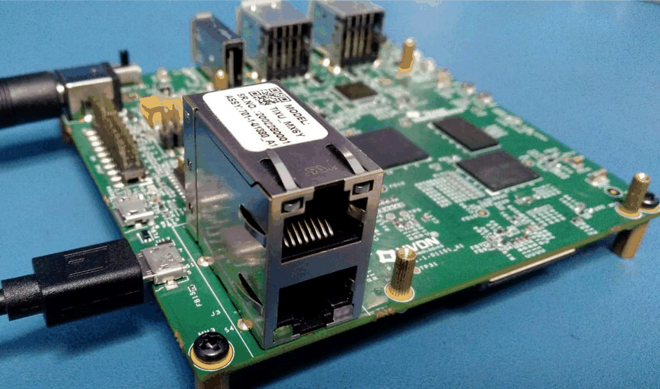
Connect micro-B side of a USB cable to debug port of the board and Type-A side to a host PC. The connections on the board at this step will look like Figure 31.

Use TeraTerm or Putty to open a Terminal and get the debug log from the device node if the host PC is running Windows. Change port number according to the COMxx port found in Device Manager for the FTDI chip.
For example, when I am testing this board I can select the COM7 port with a baud rate of 115200 and leave the other Putty settings as the default option.
If the debug prints are coming when the board is powered on, then that interface is working. When prompted to logon, enter ‘root’ and press the Enter key.
timx6y login: root
root@timx6y:~#
At the time of writing, the latest software/firmware version for TIDA-050043 is 3.0.1_3, which can be verified using a simple Linux command.
root@timx6y:~# fw-version
firmware version : 3.0.1_3
There are many other Linux functions and commands that are useful for testing the power supplies and consumption of TIDA-050043, and the next section provides some examples.