TIDUEW7 May 2020
- Description
- Resources
- Features
- Applications
- Design Images
- 1System Description
-
2System Overview
- 2.1 Block Diagram
- 2.2 Design Considerations
- 2.3 Highlighted Products
- 2.4 System Design Theory
- 3Getting Started, Testing Setup, and Test Results
- 4Design Files
- 5Software Files
- 6Related Documentation
3.1.2.2 Example Linux Commands for Testing TIDA-050043
To figure out which I2C devices are on the bus, where "0" means I am looking for I2C devices on channel 0 (because the TPS6521815 should be here at 0x24):
root@timx6y:~# i2cdetect -y -r 0
     0   1   2  3   4   5   6   7   8   9   a   b   c    d  e   f
00:             --  --  --  --  --  --  --  --  --  --  --  --  --
10: --  --  --  --  --  --  --  --  --  --  --  --  --  --  --  --
20: --  --  --  --  UU  --  --  --  --  --  --  --  --  --  --  --
30: --  --  --  --  --  --  --  --  --  --  --  --  --  --  --  --
40: --  --  --  --  --  --  --  --  --  --  --  --  --  --  --  --
50: --  --  --  --  --  --  --  --  --  --  --  --  --  --  --  --
60: --  --  --  --  --  --  --  --  --  --  --  --  --  --  --  --
70: --  --  --  --  --  --  --  --  --  --  --  --  --  --  --  --
To verify dynamic voltage scaling is working for the PMIC with respect to the CPU frequency of the processor, where 792 MHz corresponds to DCDC1 = 1.275 V while 900 MHz corresponds to DCDC1 = 1.325 V:
root@timx6y:~# echo userspace > /sys/devices/system/cpu/cpu0/cpufreq/scaling_governor
root@timx6y:~# echo 900000 > /sys/devices/system/cpu/cpu0/cpufreq/scaling_setspeed
root@timx6y:~# echo 792000 > /sys/devices/system/cpu/cpu0/cpufreq/scaling_setspeed
To run a current sensor application and measure the current on any rail coming out of the TPS6521815 PMIC, where "1" in the first prompt is current sensor IC #1, "1" in the second prompt is channel 1, and "curr1_input" returns a value of 248 mA that is being used by the VDD_ARM and VDD_SOC rails:
root@timx6y:~# test_currentsensor
Enter current sensor no[1-2]: 1
Enter voltage Level[1-3]: 1
/******************************************************************************/
/*                               CURRENT SENSOR2                              */
/*            Location of node:/sys/bus/i2c/devices/2-0040/hwmon/h1mon1/      */
/******************************************************************************/
/* ========================================================================== */
/*                              VDD_SOC_IN                                    */
/* ========================================================================== */
      curr1_crit :  16380 mA
curr1_crit_alarm :  0
     curr1_input :  248 mA
       curr1_max :  16380 mA
 curr1_max_alarm :  0
       in1_input :  1104 mV
/******************************************************************************/
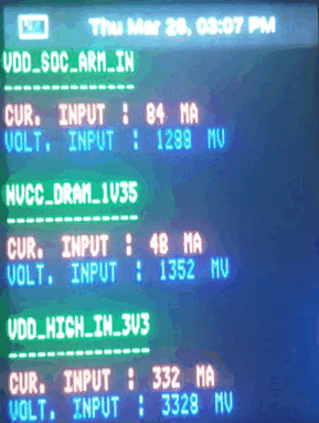
Alternatively, software has been written to set up the LCD screen and use it to display the real-time current monitoring information in addition to displaying the time configured in the real-time clock (RTC) supplied by the coin cell battery and the always-on power supply. Figure 32 shows the LCD screen during power-up, running color configurations tests, and displaying real-time current monitoring with labels and converted values.

There are many other useful functions that are written specifically for testing TIDA-050043 in addition to the thousands of pre-defined Linux commands that can be included as part of the Yocto build for iMX. The most useful one for stress testing the processor and increase load current to test the PMIC is "stress-ng." More information on Linux commands can be found in the Ubuntu manual.