TIDUEX1A December   2020  – March 2021


  1.   Description
  2.   Resources
  3.   Features
  4.   Applications
  5.   5
  6. 1System Description
    1. 1.1 Key System Specifications
  7. 2System Overview
    1. 2.1 Block Diagram
    2. 2.2 Design Considerations
    3. 2.3 Highlighted Products
      1. 2.3.1 TMP117 – High-accuracy, low-power, digital temperature sensor
      2. 2.3.2 System Design Theory
        1. 2.3.2.1 System Accuracy
  8. 3Hardware, Software, Testing Requirements, and Test Results
    1. 3.1 Hardware
    2. 3.2 Software
      1. 3.2.1 SysConfig
      2. 3.2.2 Graphical User Interface (GUI)
        1. 3.2.2.1 Launching and Running the Software
        2. 3.2.2.2 Using the GUI
          1. 3.2.2.2.1 Home Tab
          2. 3.2.2.2.2 Data Capture Tab
          3. 3.2.2.2.3 EVM Setup Tab
          4. 3.2.2.2.4 Configuration Tab
          5. 3.2.2.2.5 Register Tab
          6. 3.2.2.2.6 Collateral Tab
    3. 3.3 Testing and Results
      1. 3.3.1 Test Setup
        1. 3.3.1.1 System Accuracy
      2. 3.3.2 Test Results
  9. 4Design and Documentation Support
    1. 4.1 Design Files
      1. 4.1.1 Schematics
      2. 4.1.2 BOM
    2. 4.2 Tools and Software
      1. 4.2.1 PCB Layout Recommendations
      2. 4.2.2 Software Files
    3. 4.3 Documentation Support
    4. 4.4 Support Resources
    5. 4.5 Trademarks
  10. 5Revision History
Collateral Tab

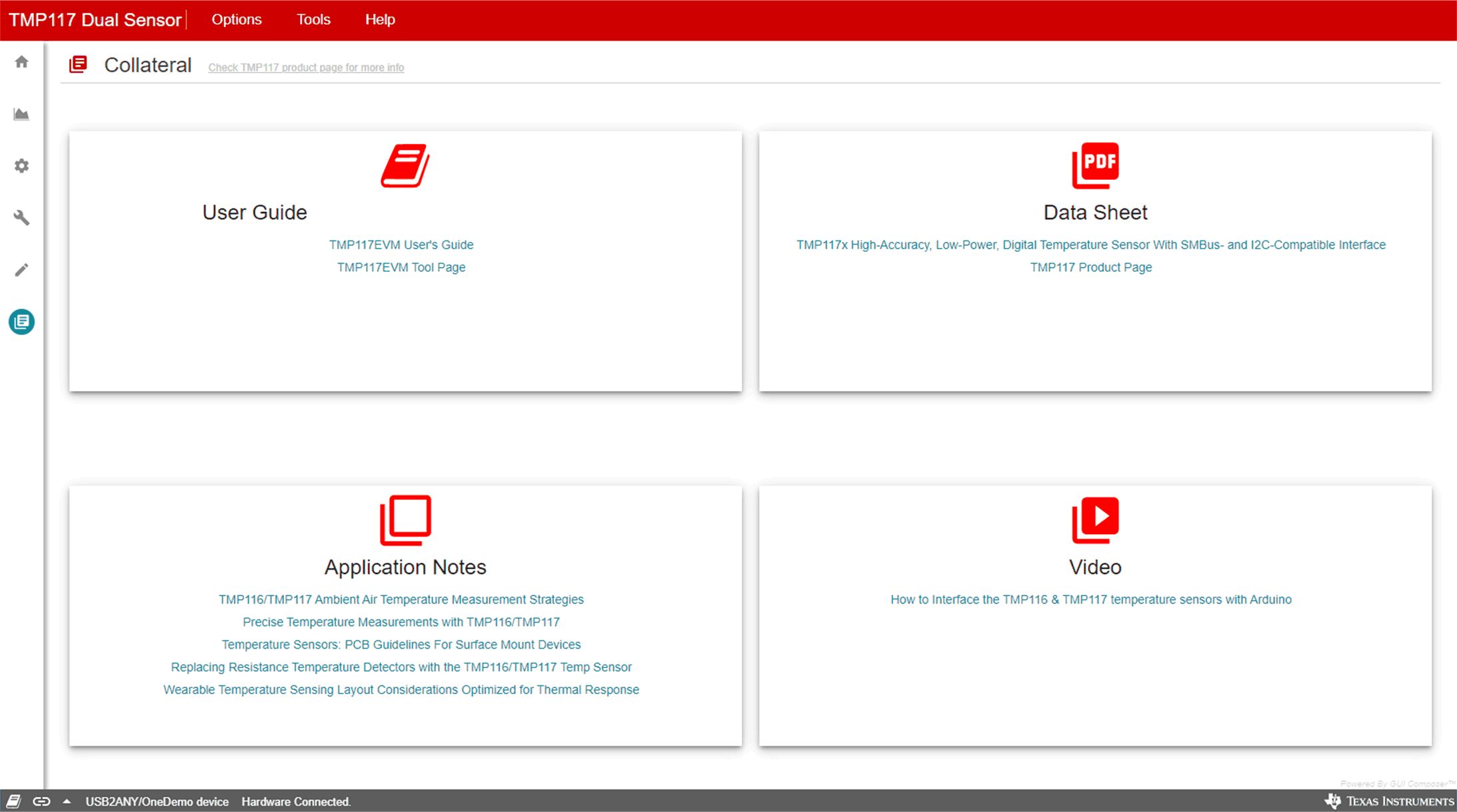
The last page of the GUI is the Collateral page, shown in Figure 3-14, which contains links to web documents pertinent to the TMP117 and its EVM. The page is divided into four sections: (1) User Guide, (2) Data sheet, (3) Application Notes, (4) Video.
GUID-20200811-CA0I-RPRS-5RNK-V8ZZPGK77C3T-low.gifFigure 3-14 Collateral Page