TIDUEY1B November 2020 – April 2024 BQ25798
- 1
- Description
- Resources
- Features
- Applications
- 6
- 1System Description
- 2System Overview
- 3Hardware, Software, Testing Requirements, and Test Results
- 4Design and Documentation Support
- 5About the Author
- 6Revision History
3.4 Test Results
At start-up, the TPS25750D PD
controller sends the initial I2C commands to set up the BQ25798 battery
charger for charging, number of cells and so on. These initial commands are based on
the answers provided on the Web-based Application Customization Tool for proper
functionality. When a 5-V sink PDO Contract is negotiated, the PD controller sets up
the buck-boost battery charger BQ25798 for a VIN of 5 V and charging the
battery at
1 A based on this particular
configuration.
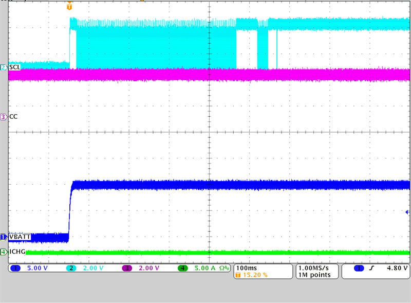 Figure 3-6 Power On Reset (POR)
Commands
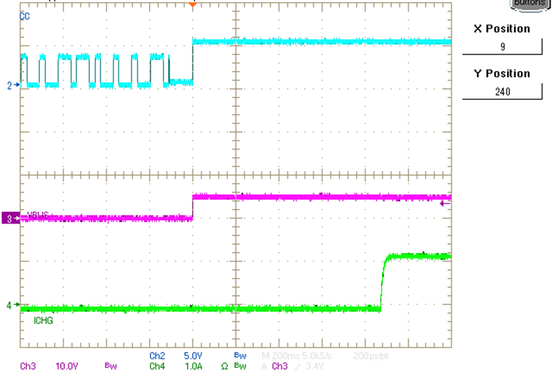 Figure 3-7 Example of a 5-V Sink
Contract Charging a Battery
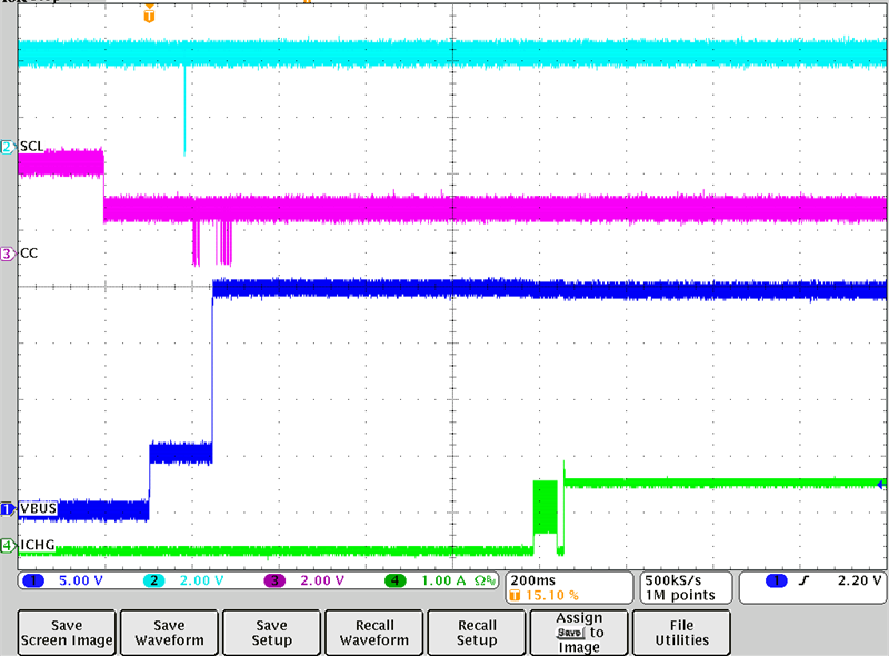 Figure 3-8 20-V Sink Charging at 1
A
Figure 3-8 20-V Sink Charging at 1
ASimilarly, when a 20 V Sink PDO contract is negotiated, the same behavior can be seen where the PD controller sets up VIN at 20 V this time, while maintaining charging at 1 A.
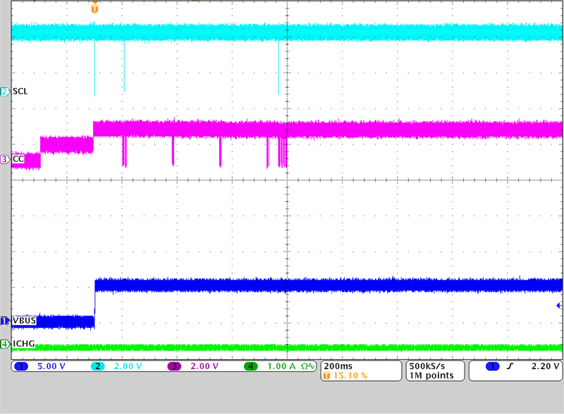 Figure 3-9 Sourcing 5 V with BQ25798 in
OTG Mode
Figure 3-9 Sourcing 5 V with BQ25798 in
OTG ModeWhen the TPS25750D negotiates a source PDO contract, the device configures the BQ25798 to operate in OTG mode so that the battery can source the power needed for the port partner. In this case, the BQ25798 needs to boost up the battery voltage up to 5 V to source power to the other device.
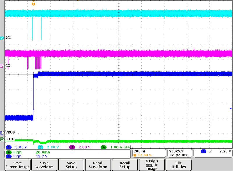 Figure 3-10 Sourcing 20 V with BQ25798 in
OTG Mode
Figure 3-10 Sourcing 20 V with BQ25798 in
OTG ModeThe same behavior can be observed when the port partner and the TPS25750D negotiate a 20 V contract using the TPS25750D as a Source.
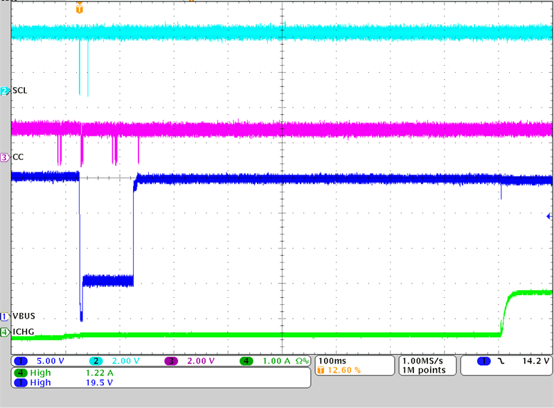 Figure 3-11 Power Role Swap from Source to
Sink
Figure 3-11 Power Role Swap from Source to
SinkOne of the features for USB Type-C PD Controllers, such as the TPS25750D is the ability to perform Power Role Swaps depending on when certain conditions change. In the corresponding figure, initially the sourcing can be observed as VBUS is at 20 V but the charging current is at 0 A, then a reset or renegotiation occurs where the PD controller needs to become a Sink and both devices accept this change. Therefore, VBUS goes to 0 V and then negotiates a 20 V Sink PDO contract. Once the Power Role Swap is done, the TPS25750D configures the BQ25798 for charging mode to charge at 1 A, which can be seen at the end of the capture.
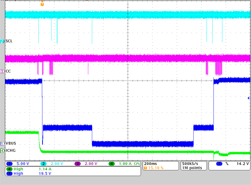 Figure 3-12 Power Role Swap from Sink to
Source
Figure 3-12 Power Role Swap from Sink to
SourceSimilarly, the same can be done in reverse order, going from the TPS25750D being a Sink and charging the battery, to renegotiating a Sourcing contract with the port partner and supplying the 20 V using the BQ25798.