TIDUEY1B November 2020 – April 2024 BQ25798
- 1
- Description
- Resources
- Features
- Applications
- 6
- 1System Description
- 2System Overview
- 3Hardware, Software, Testing Requirements, and Test Results
- 4Design and Documentation Support
- 5About the Author
- 6Revision History
3.2 Application Customization Tool
Configuration Process

Figure 3-1 TPS25750 Application Selection
First, the select the configuration depending on the application. For this reference design, choose the first option, which is selected by default as shown in Figure 3-1.
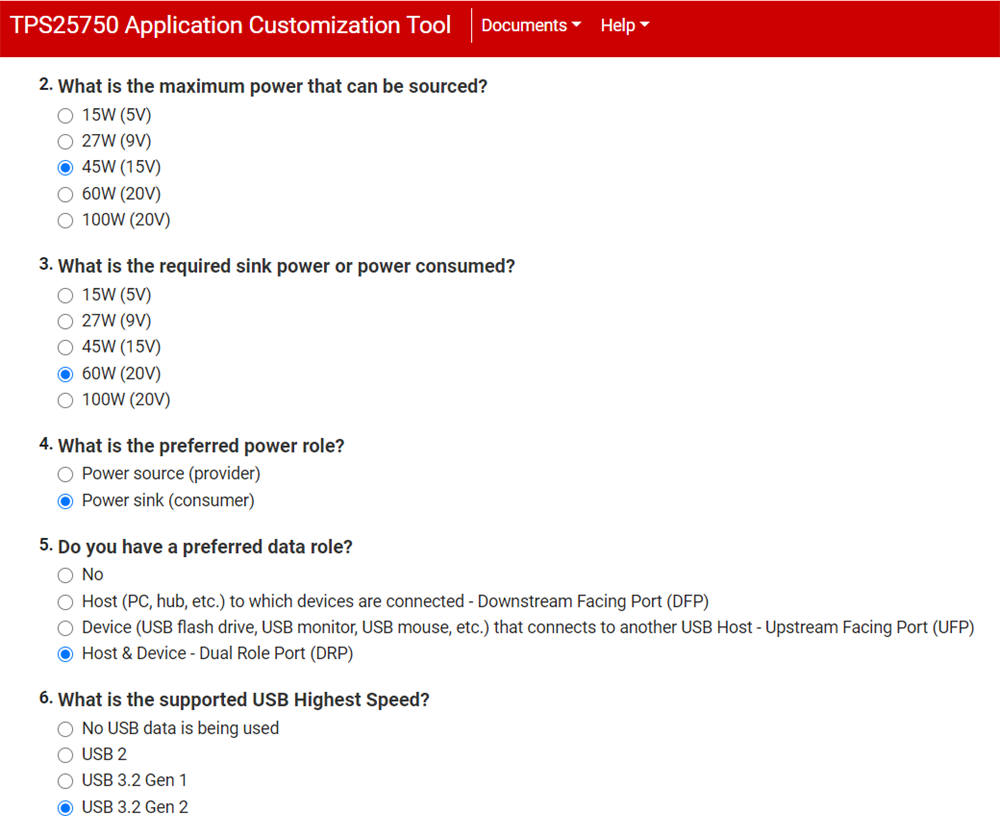
 Figure 3-2 Supported Power Questions
Questions 2 through 6 are used to set up the power and data configurations as needed for this reference design. TIDA-050047 is capable of sourcing up to 45 W (15 V, 3 A or 20 V, 2.25 A) and sinking up to 66 W. Depending on your preference, you can select the settings as you wish to test them. For this reference design, the settings shown in Figure 3-2 can be followed.
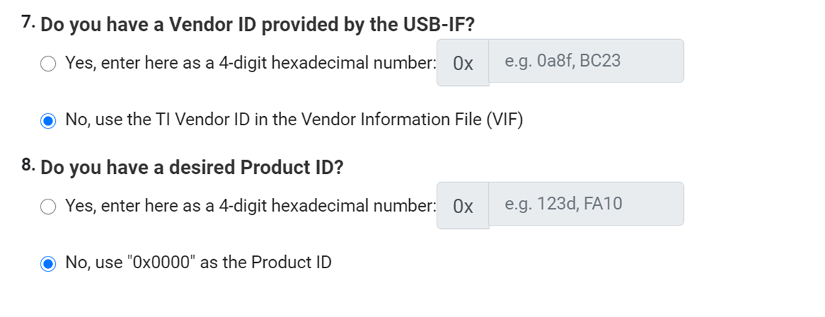
 Figure 3-3 Vendor or Product ID Information
Questions 7 and 8 pertain to the Vendor ID and Product ID, these are not necessary but if you want to input your own, you can do this here. For this project, the second option can be used for both questions.

Figure 3-4 Battery Charger Questions
The last section asks questions regarding the battery charger configuration. For this design, the battery charger used is the BQ25798, so the first option can be selected here. The following questions can be filled in to how you would want to test. For example
- Battery charging voltage you can choose to input 12 V for a 3s battery
- Battery charging current can be set to 3 A
- Charge termination current is set to a low 400 mA, this is the current that the battery charges at once the battery has reached almost full capacity
- Pre-charge current depends on the selected battery charger, select 400 mA for the BQ25798 device

Figure 3-5 Exporting the Selected Settings
When all of the questions are answered, the configuration file is ready to be programmed. There are a few options here to do so, the simplest option is to use the Aardvark™ header. Export the binary using the Generate Full Flash Binary option and then use Flash Center by Total Phase to program the selected configurations to the TPS25750D. If the customer board makes use of a TIVA chip, the binary can be flashed using Flash To Device From Current Configuration.