TIDUEY3 November 2020
2.1.2.2 Software Block Diagram of Application
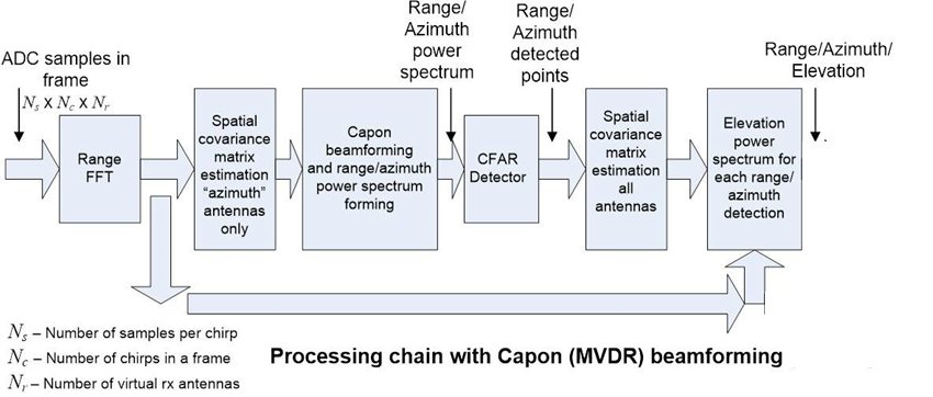
As shown in Figure 2-3, the implementation of the application demo on the AWR6843AOP consists of a signal chain running on the C674x DSP, and the tracking module running on the ARM®Cortex®-R4F processor.
At its core, the demo does two things:
- Use the radar data to produce a point cloud with each point containing a range, azimuth angle, elevation angle, and signal to noise ratio (SNR)
- Finds and determines seat occupancy status from the point cloud based on defined zone locations.
Processing Overview:
- Range processing:
- For each antenna, 1D windowing, and 1D fast Fourier transform (FFT)
- Range processing is interleaved with the active chirp time of the frame
- Implemented on HWA and Cortex R4F
- Capon Beamforming (BF):
- Static clutter removal
- Covariance matrix generation, angle spectrum generation, and integration is performed
- Outputs range-azimuth heat map
- Implemented on c674 DSP
- CFAR detection algorithm:
- Two-pass, constant false-alarm rate
- First pass cell averaging smallest of CFAR-CASO in the range domain, confirmed by second pass cell averaging smallest of CFAR-CASO in the angle domain, to find detection points.
- Implemented on c674 DSP
- Elevation Beamforming
- Capon BF algorithm is applied again for each point detected in Range-Azimuth heatmap
- 1-D Elevation Spectrum is generated and strongest signal is taken as the detected angle
- Implemented on c674 DSP
- Zone Occupancy Decision:
- Operates on point cloud
- Maps the point cloud to zone definition in a car
- For each zone, based on the number of detected points and the quality of these detected point in a zone, and the previous occupancy state, a decision of occupancy state will be updated.
- Implemented on PC as part of the visualizer
 Figure 2-3 Application Block Diagram