TIDUEY3 November   2020


  1.   Description
  2.   Resources
  3.   Features
  4.   Applications
  5.   5
  6. 1System Description
  7. 2System Overview
    1. 2.1 Block Diagram
      1. 2.1.1 Hardware Block Diagram
      2. 2.1.2 Software Block Diagram
        1. 2.1.2.1 mmWave SDK Software Block Diagram
        2. 2.1.2.2 Software Block Diagram of Application
    2. 2.2 Highlighted Products
      1. 2.2.1 AWR6843AOP
      2. 2.2.2 mmWave SDK
    3. 2.3 System Design Theory
      1. 2.3.1 Use-Case Geometry and Sensor Considerations
      2. 2.3.2 Low-Level Processing
      3. 2.3.3 High-Level Processing Details
        1. 2.3.3.1 DPM Model
        2. 2.3.3.2 Occupancy Detection State Machine
      4. 2.3.4 Output Through UART
  8. 3Hardware, Software, Testing Requirements, and Test Results
    1. 3.1 Required Hardware and Software
      1. 3.1.1 Hardware
      2. 3.1.2 Software
    2. 3.2 Testing and Results
      1. 3.2.1 Test Setup
      2. 3.2.2 Test Results
  9. 4Design Files
    1. 4.1 Schematics
    2. 4.2 Bill of Materials
    3. 4.3 Altium Project
  10. 5Software Files
  11. 6Related Documentation
    1. 6.1 Trademarks

Test Setup

Sensor Mounting Position: The sensor was mounted on the ceiling of the vehicle centered over the console separating the driver and passenger seat.
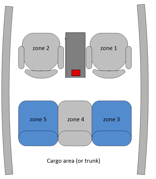
GUID-20201109-CA0I-FJ8P-XB3J-XPXSMD7J1KP6-low.png Figure 3-2 Sensor Position

Zone Definitions: Based on the mounting position of the sensor. The XYZ definitions of each zone (seat) position in the car was measured and updated in the chirp configuration file. The demo project provides example chirp configurations for each use case and supported device. These files are located in the /chirp_configs folder of the demo. NOTE: Due to variations in mounting position and vehicle geometries, users should measure and update zone definitions for their test setup in the configuration file. Details are provided in the demo user guide with the downloaded software.