TIDUEY4D August 2022 – December 2022
- Description
- Resources
- Features
- Applications
- 5
- 1System Description
- 2System Overview
- 3Hardware, Software, Testing Requirements, and Test Results
- 4FOTA Example
- 5Design and Documentation Support
- 6Terminology
- 7About the Author
- 8Revision History
3.4.1 Loading the Custom Bootloader and Application to Flash using CCS
- Set the Launchpad in Flash boot mode by moving GPIO24 to OFF (1) and GPIO32 to OFF (1) on boot select switch. Refer to the C2000™Piccolo™F28004x Series LaunchPad™ Development Kit user's guide or C2000™Piccolo™ F28003x Series LaunchPad™ Development Kit for details.
- Apply power to the board by connecting the micro USB cable to the computer and the Launchpad.
- Use CCS to download the custom bootloader to Flash bank 0.
- With F28004x, program the Bank0_LDFU_ROM build configuration .out of the custom bootloader (located at <C2000Ware_DigitalPower_SDK_path>\c2000ware\driverlib\f28004x\examples\flash\CCS) using CCS.
- With F28003x, program the Bank0_LDFU build configuration .out of the custom bootloader (located at <C2000Ware_DigitalPower_SDK_path>\solutions\tidm_02011\f28003x\examples\flash\CCS) using CCS.
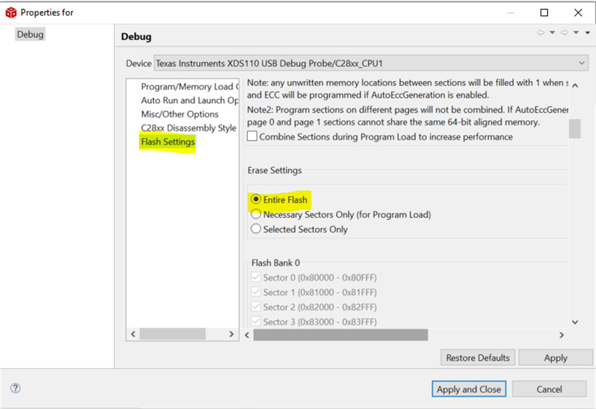
For this step, use a target configuration file that erases the entire Flash. Refer to Figure 3-2 for details.
 Figure 3-2 Target Configuration File with Erase Settings to Erase Entire Flash
- Once the custom bootloader is programmed in Flash, click on Run in CCS, and then execute the following commands from a windows command prompt:
- cd <C2000Ware_DigitalPower_SDK_path>\c2000ware\utilities\flash_programmers\serial_flash_programmer
- On F28004x: serial_flash_programmer_appln.exe -d f28004x -k f28004x_fw_upgrade_example\flashapi_ex2_sci_kernel-CPU1-RAM.txt -a buck_F28004x_lfuBANK1FLASH.txt -b 9600 -p COM11
- On F28003x: serial_flash_programmer_appln.exe -d f28003x -k f28004x_fw_upgrade_example\flashapi_ex2_sci_kernel-CPU1-RAM.txt -a buck_F28003x_lfuBANK1FLASH.txt -b 9600 -p COM11
- In the above command, f28004x_fw_upgrade_example\flashapi_ex2_sci_kernel-CPU1-RAM.txt is needed but not used. This is because the serial_flash_programmer_appln.exe is used, which programs only the application firmware, not the kernel.
- Also note that in the above command, “COM11” will have to be replaced with the specific COM port associated with your connection. This can be identified through Device Manager – Ports – XDS110 Class Application/User UART
- Enter “8 – Live DFU” – this will program the Bank1_Flash build configuration of the application firmware to Flash Bank1
- Enter “0 – Done” when complete
At this point, the custom bootloader is programmed on Flash bank 0 and the application is programmed on Flash bank 1.
- Next the custom bootloader is programmed on Flash bank 1 and the application on Flash bank 0. Use CCS to download the custom bootloader to Flash bank 1. With F28004x, program the Bank1_LDFU_ROM build configuration .out of the custom bootloader (located at <C2000Ware_DigitalPower_SDK_path>\c2000ware\driverlib\f28004x\examples\flash\CCS) using CCS. With F28003x, program the Bank1_LDFU build configuration .out of the custom bootloader (located at <C2000Ware_DigitalPower_SDK_path>\solutions\tidm_02011\f28003x\examples\flash\CCS) using CCS.
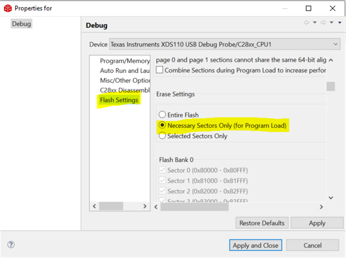
For this step, use a target configuration file that erases only the necessary sectors, not the entire Flash. Refer to Figure 3-3 for details.
 Figure 3-3 Target Configuration File with Erase Settings to Erase Necessary Sectors Only
 - Once the custom bootloader is programmed in Flash, click on Run in CCS, and then execute the following commands from a windows command prompt:
- cd <C2000Ware_DigitalPower_SDK_path>\c2000ware\utilities\flash_programmers\serial_flash_programmer
- On F28004x: serial_flash_programmer_appln.exe -d f28004x -k f28004x_fw_upgrade_example\flashapi_ex2_sci_kernel-CPU1-RAM.txt -a buck_F28004x_lfuBANK0FLASH.txt -b 9600 -p COM11
- On F28003x: serial_flash_programmer_appln.exe -d f28003x -k f28004x_fw_upgrade_example\flashapi_ex2_sci_kernel-CPU1-RAM.txt -a buck_F28003x_lfuBANK0FLASH.txt -b 9600 -p COM11
- In the above command, f28004x_fw_upgrade_example\flashapi_ex2_sci_kernel-CPU1-RAM.txt is needed but not used. This is because the serial_flash_programmer_appln.exe is used, which programs only the application firmware, not the kernel.
- Also note that in the above command, “COM11” will have to be replaced with the specific COM port associated with your connection. This can be identified through Device Manager – Ports – XDS110 Class Application/User UART
- Enter “8 – Live DFU” – this will program the Bank0_Flash build configuration of the application firmware to Flash Bank0
- Enter “0 – Done” when complete
- Reset the board. Now both Flash banks have custom bootloaders and Application Images.