TIDUEY4D August 2022 – December 2022
- Description
- Resources
- Features
- Applications
- 5
- 1System Description
- 2System Overview
- 3Hardware, Software, Testing Requirements, and Test Results
- 4FOTA Example
- 5Design and Documentation Support
- 6Terminology
- 7About the Author
- 8Revision History
3.5.2 Running the LFU Demo with Control Loop Running on the CLA
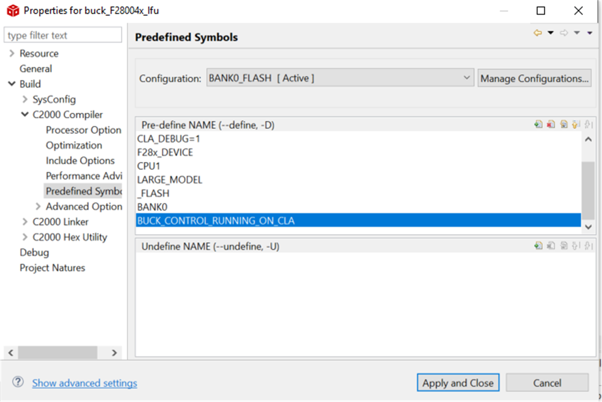
If the user wants to generate the .txt files for the projects built with the control loop running on the CLA, the only change necessary is to change the pre-defined compiler symbol BUCK_CONTROL_RUNNING_ON_CPU to BUCK_CONTROL_RUNNING_ON_CLA. Refer to Figure 3-6 for details. The generated .txt file is renamed with a _cla to distinguish it from the corresponding .txt file running on the CPU.
 Figure 3-6 Pre-defined Symbol for CLA Build of Project
Once the user has run the LFU demo with the Control loop running on the CPU, running the LFU demo with the Control loop running on the CLA is straightforward, and attention needs to be paid to only a few points:
- If the device already contains the Application
files corresponding to the CPU side control loop, this update can be made using
the same LFU commands as in the previous section, except with the updated .txt
names corresponding to the CLA build (mentioned in Table 3-1). For example, when updating from BANK0_FLASH to BANK1_FLASH, execute the
command:
- On F28004x: serial_flash_programmer_appln.exe -d f28004x -k f28004x_fw_upgrade_example\flashapi_ex2_sci_kernel-CPU1-RAM.txt -a buck_F28004x_lfuBANK1FLASH_cla.txt -b 9600 -p COM11
- On F28003x: serial_flash_programmer_appln.exe -d f28003x -k f28004x_fw_upgrade_example\flashapi_ex2_sci_kernel-CPU1-RAM.txt -a buck_F28003x_lfuBANK1FLASH_cla.txt -b 9600 -p COM11
- The CLA setup function occurs in main() on a device reset (not after an LFU switch), so it is important to reset the device after running the LFU, so that this initialization is performed. For example, with control loop running on the CPU, assume that BANK0_FLASH was updated last. This means the firmware on BANK0 is executing. So the user will need to execute the LFU command to update BANK1_FLASH (with the CLA side executable). After the LFU update is complete, a device reset is required. The device reset needs to be done only once.
Then the user can perform additional LFU updates with the CLA side firmware executables, without device reset.
- Figure 3-7 and Figure 3-8 demonstrate LFU switchover with the Control loop running on the CLA. There is a background task that toggles a GPIO every 1ms, and this GPIO is available on header J4 of the Launchpad, signal 33. Note how the LFU switchover in this case can, in general, overlap with ISR execution, because the ISR executes on the CLA whereas LFU occurs on the CPU. This is not an issue in general, but there can be scenarios where this is not acceptable. The signals shown in Figure 3-7 and Figure 3-8 are LFU switchover, CLA ISR load, CLA background task execution, and the regulated output voltage.
 Figure 3-7 LFU Switchover Timing – Control loop on CLA
 Figure 3-8 CLA Background Task