TIDUEY9 April   2021


  1.   Description
  2.   Resources
  3.   Features
  4.   Applications
  5.   5
  6. 1System Description
  7. 2System Overview
    1. 2.1 Block Diagram
    2. 2.2 Design Considerations
    3. 2.3 Highlighted Products
      1. 2.3.1 LP8770
        1. 2.3.1.1 Safety Features
          1. 2.3.1.1.1 Window Watchdog
          2. 2.3.1.1.2 Voltage Monitoring
      2. 2.3.2 AWR1843/xWR6843 mmWave Sensor Solution
    4. 2.4 System Design
      1. 2.4.1 Hardware Block Diagram
      2. 2.4.2 Software Components
        1. 2.4.2.1 Secondary Bootloader (SBL)
        2. 2.4.2.2 mmWaveLink APIs
        3. 2.4.2.3 mmWave Safety Diagnostic Library (SDL)
        4. 2.4.2.4 mmWave SDK Software Block Diagram
  8. 3Hardware, Software, Testing Requirements, and Test Results
    1. 3.1 Hardware Requirements
    2. 3.2 Test Setup
    3. 3.3 Test Results
  9. 4Design and Documentation Support
    1. 4.1 Design Files
      1. 4.1.1 Schematics
      2. 4.1.2 BOM
    2. 4.2 Tools and Software
    3. 4.3 Documentation Support
    4. 4.4 Support Resources
    5. 4.5 Trademarks
  10. 5About the Author

Hardware Block Diagram

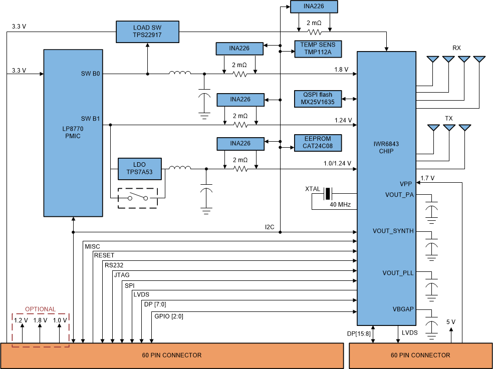
The TIDEP-01025 is implemented for AWR1843BOOST, AWR6843ISK and IWR6843ISK EVM. The EVM needs to be connected to a host PC through universal asynchronous receiver-transmitter (UART) for MetaImage load and log collection.

The AWR1843BOOST/xWR6843ISK includes the following features:

  1. AWR1843 Radar Device on AWR1843BOOST, IWR6843/AWR6843 Radar Device on xWR6843ISK.
  2. Power management circuit to provide all the required supply rails from a single 5-V input
  3. Three onboard TX antennas and four RX antennas
  4. Onboard XDS110 that provides a JTAG interface, UART for sending Diagnostic test and Monitor report from mmWave device.
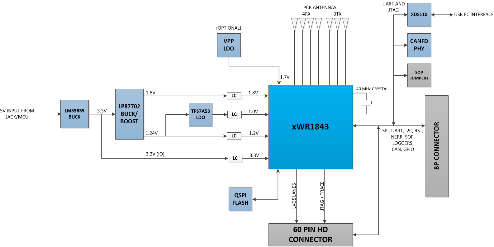
GUID-8F06DC77-D011-4609-A946-0685F6A8D466-low.png Figure 2-4 Block Diagram AWR1843BOOST
GUID-01058B8B-5C4F-46B1-A865-4306B70D1168-low.gif Figure 2-5 Block Diagram of xWR6843ISK

For more details on the hardware, see the following:

  1. AWR1843 Evaluation Module (AWR1843BOOST) Single-Chip
  2. AWR6843 Evaluation Module (AWR6843ISK) Single-Chip
  3. IWR6843 Evaluation Module (IWR6843ISK) Single-Chip
  4. mmWave Sensing Solution

The schematics and design database can be found in the following documents:

  1. AWR1843 Evaluation Board Design Database
  2. AWR1843BOOST Schematic, Assembly, and BOM
  3. xWR6843BOOST Schematic, Assembly, and BOM