TIDUEZ1 March 2021
- Description
- Resources
- Features
- Applications
- 5
- 1System Description
-
2System Overview
- 2.1 Block Diagram
- 2.2
Design Considerations
- 2.2.1 Multichannel SSR with Independent Isolation Between SSR Channels
- 2.2.2 Design Challenge With Single Isolation
- 2.2.3 Multichannel SSR Drive With Single Isolation Multichannel Digital Isolator
- 2.2.4 Need of High-Impedance Voltage Translator
- 2.2.5 Design to Minimize Cross-Coupling and MOSFET Gate Pick up Due to Other SSR Switching
- 2.2.6 Schematic: Design of Gate-Drive Circuit
- 2.2.7 Schematic: Digital Isolator Circuit
- 2.2.8 Schematic: 3.3 V to 10V_ISO, 5V_ISO Power Supply
- 2.3 Highlighted Products
- 3Hardware, Software, Testing Requirements, and Test Results
- 4Design and Documentation Support
- 5About the Author
3.3.2 Overcurrent Testing With External Fuse
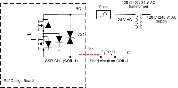
The reference design is tested for short-circuit conditions with an external fuse. Figure 3-17 shows the wiring diagram during testing. The short circuit is created by shorting the relay coil (COIL-1).
 Figure 3-17 Overcurrent Protection Circuit
With External Fuse
Figure 3-17 Overcurrent Protection Circuit
With External FuseTest Condition:
- The COIL-1 is short-circuited
- The short-circuit current at the secondary of the transformer is limited by the secondary short-circuit impedance of transformer
- Specification of the transformer used for
testing:
- Manufacturer part number: 4000-09C02K999 (TE connectivity - laminated 20VA transformer)
- Secondary winding resistance = 2 Ω
- Specification of the fuse used in series with the
transformer secondary line RC:
- Manufacturer part number: 046601.5NR (Littelfuse Inc.)
- Rating: 1.5 A, 63-V AC/DC board mount fuse, 1206
- Response time: Fast blow. Melting I²t: 0.1103
Observations during testing:
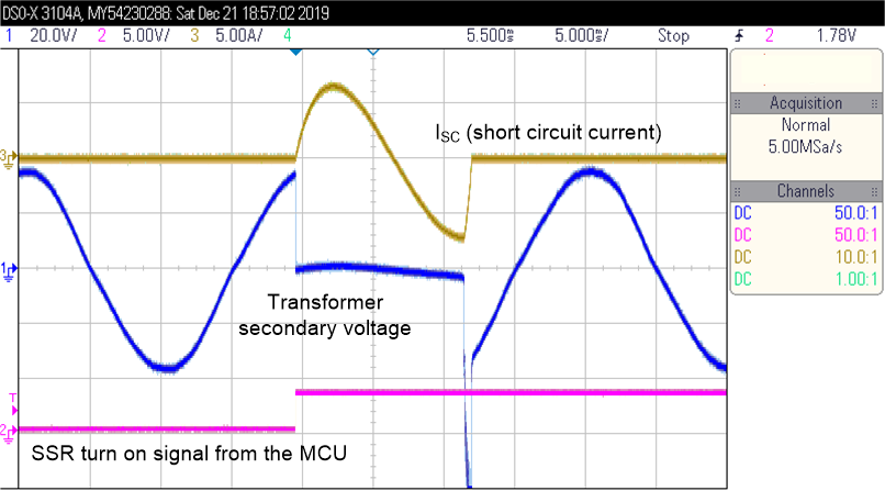
- During the short-circuit test, the fuse was blown within one electrical cycle (< 20 ms) with peak short-circuit current of approximately 7 A. The SSRs were functional after testing.
- Figure 3-18 shows the test result waveforms.
 Figure 3-18 Short-Circuit Test Waveforms
With External Fuse