TIDUEZ4 May   2021


  1.   Description
  2.   Resources
  3.   Features
  4.   Applications
  5.   5
  6. 1System Description
  7. 2System Overview
    1. 2.1 Block Diagram
    2. 2.2 Highlighted Products
      1. 2.2.1 SimpleLink MCU
        1. 2.2.1.1 CC3235MODS
        2. 2.2.1.2 CC1352R LaunchPad
          1. 2.2.1.2.1 CC1352R
      2. 2.2.2 Power
        1. 2.2.2.1 TPS63802
        2. 2.2.2.2 TPS63900
        3. 2.2.2.3 TPS62825
        4. 2.2.2.4 TPS7A03
        5. 2.2.2.5 TPS7A20
        6. 2.2.2.6 TPS62840
        7. 2.2.2.7 TPS22919
        8. 2.2.2.8 LM66100
      3. 2.2.3 Peripherals
        1. 2.2.3.1 OPT3004
        2. 2.2.3.2 DRV8837C
        3. 2.2.3.3 TPA2011
        4. 2.2.3.4 TLV61048
      4. 2.2.4 OmniVision Video Encoder OA7000
      5. 2.2.5 OmniVision Image Sensor SP2329
      6. 2.2.6 YTOT Lens Module
    3. 2.3 Design Considerations
      1. 2.3.1  Input Power: Battery and USB
      2. 2.3.2  Power Requirements
      3. 2.3.3  Camera Wake-up and Day or Night Sensing
        1. 2.3.3.1 PIR and MSP430 Based Motion Detection Design for Low Cost and High Performance
      4. 2.3.4  Battery Gauging
      5. 2.3.5  IR LED Illumination
      6. 2.3.6  IR Cut Filter
      7. 2.3.7  Audio
      8. 2.3.8  System Operation
      9. 2.3.9  Wi-Fi and Host Subsystem
      10. 2.3.10 Firmware Control
        1. 2.3.10.1 Application Flow
  8. 3Hardware, Software, Testing Requirements, and Test Results
    1. 3.1 Hardware
    2. 3.2 Software
    3. 3.3 Setup
      1. 3.3.1 Configuration Steps for Video over Wi-Fi
      2. 3.3.2 (Optional) Flash OA7000 With Latest Firmware or Stream Video Over USB
      3. 3.3.3 Audio Streaming
      4. 3.3.4 LPSTK-CC1352R Configuration Steps for Camera Module
    4. 3.4 Test Results
      1. 3.4.1 Power Supply Rails and Current Consumption
      2. 3.4.2 Battery Life Calculations
      3. 3.4.3 Video Streaming
      4. 3.4.4 IR LED Drive
  9. 4Design and Documentation Support
    1. 4.1 Design Files
      1. 4.1.1 Schematics
      2. 4.1.2 Bill of Materials
    2. 4.2 Software
    3. 4.3 Support Resources
    4. 4.4 References
    5. 4.5 Trademarks
  10. 5About the Author

IR LED Illumination

The CC3235MODS can be configured to enable the IR illumination at night, based on feedback from ambient light sensor. This powers-up the IR LED driver from the battery rail via load switch TPS22919.

Note: It is recommended to not enable IR illumination while using power from the USB port as the IR LED current requirement may exceed the output current of the USB port.

IR LEDs are connected using the CN8 connector. IR LED dimming can be regulated by driving an external PWM input at LED_PWM.
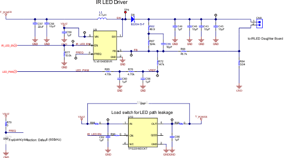
GUID-20210422-CA0I-PTTL-9GXB-PSHN3BNNBQJW-low.gif Figure 2-23 IR LED Driver Circuit in the Design

Typical design use-cases for IR LED SFH4715A are listed in Table 2-3:

Table 2-3 Design Use-Cases for IR LED SFH4715A
IR LED FORWARD CURRENT TYPICAL FORWARD VOLTAGE TOTAL FORWARD VOLTAGE ACROSS 6 LEDs EFFICIENCY OF LED DRIVER TLV61048 CALCULATED INPUT CURRENT EXPECTED TO BE DRAWN FROM BATTERY
500 mA 1.54 V 9.26 V 90% 1.56 A
100 mA 1.4 V 8.4 V 90% 0.3 A
1 A 1.7 V 10.2 V 90% 3.4 A